
Summary of Contents for Technifor UC500
- Page 1 OPERATING AND MAINTENANCE MANUAL UC500 CONTROL UNIT FOR MARKING MACHINES Technifor reserves all rights to modify its products. www.technifor.com This document is non contractual.
-
Page 2: Table Of Contents
Table of contents A - Introduction ........................3 1. Foreward ..............................3 2. Unpacking .............................. 3 3. Identification of the marking equipment ....................4 4. Regulation observance ........................... 4 Declaration of CE compliance ......................4 Declaration of incorporation ......................4 Declaration of compliance to other directives ................... -
Page 3: A - Introduction
This Control Unit is exclusively used to operate Technifor marking heads. If used for other purposes, Technifor does not guarantee the quality of the results obtained. Technifor is not responsible for the damage the CCU may cause in case of inappropriate use. -
Page 4: Identification Of The Marking Equipment
The marking equipment is identified by: • 1 identifcation tag on the control unit Have the model and serial number of the equipment available when contacting Technifor. 4. Regulation observance Manufacturer, GravoTech Marking SAS - 56 avenue Jean Jaurès BP 80015 - 10604 LA CHAPELLE SAINT LUC -... -
Page 5: Declaration Of Compliance To Norms
This Control Unit is exclusively used to operate Technifor marking heads. If used for other purposes, Technifor does not guarantee the quality of the results obtained. Technifor is not responsible for the damage the CCU may cause in case of inappropriate use. -
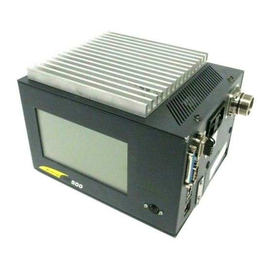
Page 6: B - Description Of The Control Unit
1. Description The Control Unit is designed to manage the markings performed by the numerically controlled heads manufactured by Technifor. It contains the control and power electronics, as well as an LCD screen. A keyboard of the type PS2 is connected to its front panel. -
Page 7: Physical Characteristics
Description of the Control Unit 2. Physical characteristics • dimensions (L x w x h): 218 mm (8.583 in) x 180 mm (7.087 in) x 150 mm (5.906 in) • weight: - pneumatic version: 3.9 kg (8.598 lb) - electromagnetic version: 4.1 kg (9.039 lb) 3. -
Page 8: Dimensional Drawings Of The Control Unit In Box Configuration
Description of the Control Unit 4. Dimensional drawings of the Control Unit in box configuration Ref. DCD01/3067 - UC500_en_D 8/27... -
Page 9: Dimensional Drawings Of The Control Unit In Rack Configuration
Description of the Control Unit 5. Dimensional drawings of the Control Unit in rack configuration Ref. DCD01/3067 - UC500_en_D 9/27... -
Page 10: List Of Accessories Available Upon Request
15 m (49.212 ft) Head/CCU connecting cable MCOLE300/38 RS232 cable Ref. • Used to connect the UC500 to the serial port of a PC or an automaton for data transfer. MCORS109/9 UC500 version rack 19" 5U Ref. • Used to integrate the CCU in a cabinet. - Page 11 T5070004 T5070004 T5070004 Font dot by dot - Medium density T5070005 T5070005 T5070005 Font dot by dot - High density T5070006 T5070006 T5070006 For more information about custom font designs, contact Technifor or the distributor. Ref. DCD01/3067 - UC500_en_D 11/27...
-
Page 12: C - Communication
Communication 1. RS232 cable Sub. D9F Sub. D9F Grounding Grounding 2 m (6.56 ft) Metallic SubD9F for shielded cables 2. Dedicated Inputs/Outputs Wiring of the female 9 SubD connector This connector allows to communicate with the machine. It contains dedicated All-or-Nothing Inputs and Outputs. They are used in the marking cycle. -
Page 13: Connection Diagram For The Dedicated Inputs / Outputs
Communication Connection diagram for the dedicated Inputs / Outputs SubD 9F Machine Communication CCU side Start marking External contact Stop marking External contact Marking in progress External light Marking in progress Fault External light Machine ready External light Common Relay Note In the diagram above, the Inputs are wired to the internal power supply, available on the connector of the CCU (+ 24 V DC). -
Page 14: Description Of The Communication Signals
Communication Description of the communication signals • Start marking (Input) - To activate the "Start marking" Input, establish a zero potential electrical connection between pins 4 and 5. - This connection must not be inferior to 500 ms nor superior to the cycle time of the marking file. •... -
Page 15: Timing Diagrams Of The Communication Signals
Communication Timing diagrams of the communication signals Operating mode with the internal program T05 Launch a "Start cycle" Close the dry contact between pins 4 and 5. Stop the cycle Open the dry contact (usually closed) between pins 9 and 5. Obtain the "End of cycle"... - Page 16 Communication • Maintained mode: Impulse Start cycle Marking End of marking cycle Information Marking in progress Marking Marking Ready to marking File loaded Ref. DCD01/3067 - UC500_en_D 16/27...
- Page 17 Communication • Pulse mode: Impulse Start cycle Marking End of marking cycle Information Marking in progress Marking Marking Ready to marking File loaded Ref. DCD01/3067 - UC500_en_D 17/27...
-
Page 18: Generic Inputs/Outputs
Communication 3. Generic Inputs/Outputs Wiring of the female 25 SubD connector This connector allows the connection of generic Inputs/Outputs. Use exclusively shielded cable. Connect the shielding to the electrical ground on either side of the cable. Pin functions Number Description + 24 V - 300 mA max. -
Page 19: Characteristics Of The Inputs
• consumption and operating range of the Inputs - applicable voltage per Input: 12 V - 24 V - intensity consumed per Input: approximately 5 mA • wiring of 8 inputs with power supplied by UC500 Negative reference (common) 3 (6) -
Page 20: Characteristics Of The Outputs
Communication • wiring of 8 inputs with power supplied by the user + 24 V DC power supply Negative reference (common) 3 (6) Negative reference (common) 7 (19) + 24 V DC power supply Internal connections Characteristics of the Outputs 4 Outputs of the type NPN with open collector are available. -
Page 21: Usb-A Key
Communication Wiring of 4 outputs with power supplied by the user Relay or solenoid valve(s) Max 1 W per connection + shielded charge with freewheeling diode + 24 V DC power supply Relay or sole- noid valve(s) Max 1 W per Output O0-O1 (8;9) connection + shielded charge... -
Page 22: D - Installation
Installation 1. Connections If the CCU is placed on a table or a workbench, imperatively mount the feet before the power up. The feet provide clearance for the air passages under the CCU. The different elements of the equipment must be connected with the power off. The power supply should be connected last. -
Page 23: Connection Of The Marking Head To The Ccu
Installation 4. Connection of the marking head to the CCU Connect the marking head and the CCU via their connection cable. Firmly insert the plugs, and tighten the locking rings. Check that the connection is appropriate. 5. Power supply connection •... -
Page 24: Assembling The Mounting Plates
Installation Assembling the mounting plates (Case of the CCU installed at the back of a cabinet) The back panel of the CCU has 4 mounting holes. A screw is already attached in one of these holes. • Remove this screw. •... -
Page 25: Ccu Assembly In Rack Configuration
Installation CCU assembly in rack configuration To perform the assembly, imperatively use the mounting kit provided. • Attach the mounting brackets to the rackable panel. • Remove the feet that may be attached to the CCU. • Place the CCU on the brackets. •... -
Page 26: E - Preventive Maintenance
Preventive maintenance Turn off the CCU before any intervention. 1. Changing the fuse Turn off the CCU before any intervention. Unplug the power supply cord. Extract the fuse holder with 2 screwdrivers. Insert the new fuse. Pneumatic machines Power Power supply Ref. -
Page 27: F - Appendix
E-mail: tfgmbh@gmbh.technifor.com E-mail: info@technifor.it Fax : (44) 19 26 88 31 05 E-mail: sales@ltd.technifor.com SPAIN AUSTRIA SWITZERLAND Technifor Marcadores Industriales SL GravoTech GmbH Gravograph Switzerland C/ Sant Iscle, 29 bajos B Porschestra ß e Champ Olivier 2 08031 BARCELONA 3106 ST PÖLTEN Ch 3280 MORAT Tel.
Need help?
Do you have a question about the UC500 and is the answer not in the manual?
Questions and answers