Table of Contents
Advertisement
USER MANUAL
C
U
ONTROLLER
SER
I
M
NTERFACE
ANUAL
®
X
S
PART NUMBER:
02250180-094 R00
KEEP FOR
FUTURE
WARRANTY NOTICE
REFERENCE
SULLAIR CORPORATION
©
Failure to follow the instructions
The information in this manual is current
and procedures in this manual or,
as of its publication date and applies to
misuse of this equipment will
controller part number :
VOID its warranty!
88290018-640 R03
and all subsequent serial numbers.
Advertisement
Table of Contents

Related Manuals for Sullair ShopTek


Summary of Contents for Sullair ShopTek
- Page 1 PART NUMBER: 02250180-094 R00 KEEP FOR FUTURE WARRANTY NOTICE REFERENCE SULLAIR CORPORATION © Failure to follow the instructions The information in this manual is current and procedures in this manual or, as of its publication date and applies to misuse of this equipment will...
- Page 2 AIR CARE SEMINAR TRAINING Sullair Air Care Seminars are courses that provide hands-on instruction for the proper operation, maintenance, and servicing of Sullair products. Individual seminars on Industrial compressors and compressor electrical systems are offered at regular intervals throughout the year at Sullair’s corporate headquarters training facility located at Michigan City, Indiana.
-
Page 3: Table Of Contents
TABLE OF CONTENTS SECTION 1—SAFETY GENERAL PERSONAL PROTECTIVE EQUIPMENT PRESSURE RELEASE FIRE AND EXPLOSION MOVING PARTS HOT SURFACES, SHARP EDGES AND SHARP CORNERS TOXIC AND IRRITATING SUBSTANCES ELECTRICAL SHOCK LIFTING 1.10 ENTRAPMENT SECTION 2—STARTUP PROCEDURES INTRODUCTION CONTROLLER PANEL LAYOUT START UP PROCEDURES SHUTDOWN PROCEDURE SECTION 3—ADJUSTMENTS INTRODUCTION... - Page 4 TABLE OF CONTENTS NORMAL VIEW SERVICE REMINDERS NORMAL VIEW WARNING MESSAGE FAULT MESSAGES SECTION 5—TROUBLESHOOTING TROUBLESHOOTING INTRODUCTION TROUBLESHOOTING GUIDE MACHINE BEHAVIOR AFTER A POWER INTERRUPTION...
-
Page 5: Section 1-Safety
GENERAL tions relative to personal protective equipment, such as eye and face protective equipment, Sullair Corporation and its subsidiaries design and respiratory protective equipment, equipment manufacture all of their products so they can be intended to protect the extremities, protective operated safely. -
Page 6: Moving Parts
SECTION 1 inside diameter to reduce pressure in case of accumulate on, under or around acoustical mate- hose failure. rial, or on any external surfaces of the air com- pressor. Wipe down using an aqueous industrial D. Flow-limiting valves are listed by pipe size and cleaner or steam clean as required. -
Page 7: Hot Surfaces, Sharp Edges And Sharp Corners
SECTION 1 C. Wear snug-fitting clothing and confine long hair when working around this compressor, especially DANGER when exposed to hot or moving parts. D. Keep access doors, if any, closed except when making repairs or adjustments. E. Make sure all personnel are out of and/or clear of the compressor prior to attempting to start or operate it. -
Page 8: Electrical Shock
SECTION 1 swallowed, induce vomiting by administering a tablespoon of salt, in each glass of clean, warm water until vomit is clear, then administer two DANGER teaspoons of baking soda in a glass of clean water. Have patient lay down and cover eyes to exclude light. -
Page 9: 1.10 Entrapment
SECTION 1 Keep lift operator in constant attendance when- N. Make sure pallet-mounted compressors are ever compressor is suspended. firmly bolted or otherwise secured to the pallet prior to attempting to forklift or transport them. J. Set compressor down only on a level surface NEVER attempt to forklift a compressor that is capable of safely supporting at least its weight not secured to its pallet, as uneven floors or sud-... - Page 10 NOTES...
-
Page 11: Introduction
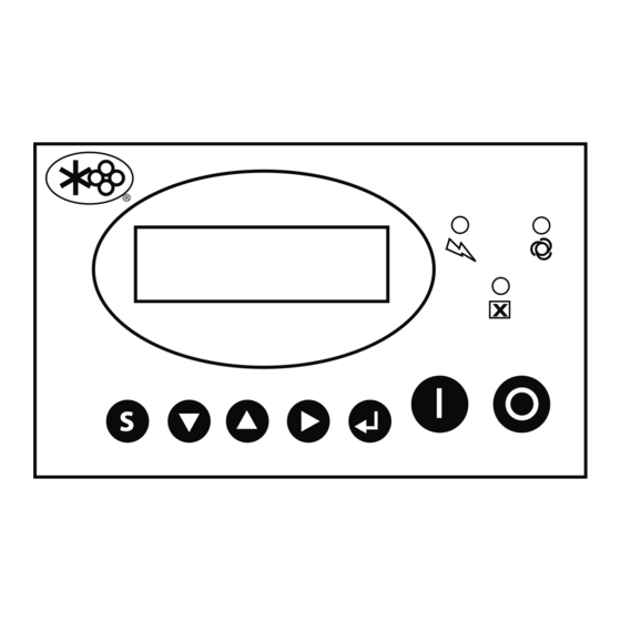
CONTROLLER USER INTERFACE MANUAL ™ Section 2 STARTUP PROCEDURES INTRODUCTION the compressor operation. Up Arrow Pad —Used to navigate “up” the list This compressor is equipped with a Controller for controlling the compressor system operation, setting of display messages and to increase or change parameter values for adjustments. - Page 12 CONTROLLER USER INTERFACE MANUAL SECTION 2 ™ START UP PROCEDURES 4. Exchange any two of the three fan motor leads at the fan motor starter. Refer to the COMPRESSOR MOTOR ROTATION compressor User’s Manual. DIRECTION CHECK ( 5. Recheck the direction of the fan motor. INSTALLATION INITIAL START-UP AFTER After the compressor has been installed and the...
-
Page 13: Shutdown Procedure
SECTION 2 CONTROLLER USER INTERFACE MANUAL ™ SHUTDOWN PROCEDURE SUBSEQUENT START-UP PROCEDURE 1. On subsequent start-ups, check the fluid Shut down the compressor by pressing the STOP sight glass for proper fluid level. Service if pad on the Controller panel. necessary. - Page 14 NOTES 02250180-094 R00...
-
Page 15: Introduction
CONTROLLER USER INTERFACE MANUAL ™ Section 3 ADJUSTMENTS INTRODUCTION 2. Use the UP arrow or DOWN arrow pad to navigate to the parameter to be This section describes steps for using the Controller to modify specific parameters that control the changed. -
Page 16: User Adjustable Control Parameters
CONTROLLER USER INTERFACE MANUAL SECTION 3 ™ will run unloaded in AUTO mode before shutting off. 7. Press ENTER pad to return to the nor- STOP DELAY TIME – Set time (sec) that machine mal view. will continue to run after pressing the stop button. - Page 17 SECTION 3 CONTROLLER USER INTERFACE MANUAL ™ machines. LANGUAGE SEL – Select ENGLISH, FRENCH, SPANISH or PORTUGUESE as controller display COM ADDRESS – Communication address. language. SEQUENCE NO. – Number of compressors in POWER FREQ – Select incoming power frequency. sequencing network.
- Page 18 CONTROLLER USER INTERFACE MANUAL SECTION 3 ™ LOAD PRESS: SEQ UNLOAD PRESS: * NORMAL VIEW XXXX PSI XXXX PSI UNLOAD PRESS: SEQ DELAY: * TOTAL RUN TIME: XXXX PSI XXXXS HOURS MIN LOADED TIME: MTR START TIME: LANGUAGE SEQ: * HOURS MIN XXXXS ENGLISH...
-
Page 19: Remote Unload
SECTION 3 CONTROLLER USER INTERFACE MANUAL ™ REMOTE UNLOAD DRAIN CONTROL The machine may be configured to allow user- Shoptek compressors equipped with furnished external remote control. This may be wired condensate drain valves however the Controller does to a remote switch, timer, or other controls to halt have capability to control a solenoid type drain valve. - Page 20 NOTES 02250180-094 R00...
-
Page 21: Introduction
CONTROLLER USER INTERFACE MANUAL ™ Section 4 DESCRIPTION INTRODUCTION Right Arrow Pad —Used to make selection in menu screen and to change digits when making This section describes the components of the changes to parameters. Controller, the function of each component, and the various types of displays that may appear on the —Used save... -
Page 22: Display Screen
Refer to Figure 4-1. The first The Display Screen will also display fault conditions screen shows “SULLAIR” along with the serial when they occur. number of the compressor. Refer to Figure 4-2. The second screen shows the total operation time of the... -
Page 23: Operating Modes
SECTION 4 CONTROLLER USER INTERFACE MANUAL ™ since the last service. FLUID – Displays the total time on the fluid since the last service. Automatic Mode AUTO LOAD (Normal View) GREASE – Displays the total time on the grease 174°F 62PSI since the last service. -
Page 24: Operating States
CONTROLLER USER INTERFACE MANUAL SECTION 4 ™ OPERATING STATES RUN MODE – Displayed after the motor is started and before delivering air. A timer is displayed which counts down the time between starting of the motor Operating States describe state compressor operation in response to the current and de-energizing of the unload solenoid. -
Page 25: Normal View Warning Message
SECTION 4 CONTROLLER USER INTERFACE MANUAL ™ machine operation specifications. FLUID CHANGE - The compressor fluid should be STOP: changed within the time frame noted in the machine RTD FAULT operation specifications. GREASE CHANGE - The grease should be changed within the time frame noted in the machine operation specifications. - Page 26 NOTES 02250180-094 R00...
-
Page 27: Troubleshooting Introduction
Sullair problems when they occur. The information Distributor or the Sullair Corporation factory Service contained in Table 5-1:Troubleshooting Guide, has Department. been compiled from factory experience and contains... -
Page 28: Machine Behavior After A Power Interruption
CONTROLLER USER INTERFACE MANUAL SECTION 5 ™ Table 5-1: Controller Troubleshooting Guide MESSAGE PROBABLE CAUSE REMEDY OIL FILTER ALM Service interval has expired. Perform recommended maintenance and reset the reminder in the controller. A-O SEPARATOR Maintenance due. AIR FILTER ALM FLUID CHANGE GREASE CHANGE E-STOP... - Page 29 NOTES...
- Page 30 Zone Des Granges BP 82 Chiwan, Shekou Michigan City, Indiana, 46360 U.S.A. 42602 Montbrison, France Shenzen, Guangdong PRV. www.sullair.com Telephone: 33-477968470 PRC POST CODE 518068 Telephone: 1-800-SULLAIR (U.S.A. only) Fax: 33-477968499 Telephone: 755-6851686 Fax: 219-874-1273 www.sullaireurope.com Fax: 755-6853473 CUSTOMER CARE www.sullair-asia.com...
Need help?
Do you have a question about the ShopTek and is the answer not in the manual?
Questions and answers