Table of Contents
Advertisement
Quick Links
- 1 Supervisor Keyboard Layout
- 2 Control Parameters- Pressure, Temperature and Timer Settings
- 3 Calibration- Correction Factors for Pressures
- 4 Troubleshooting Guide- Supervisor Controller
- 5 Wiring Diagram- Supervisor Communication Module
- 6 Wiring Diagram- Supervisor Control
- 7 Supervisor Display and Menus
- Download this manual
Advertisement
Table of Contents

Related Manuals for Sullair SUPERVISOR CONTROLLER Series


Summary of Contents for Sullair SUPERVISOR CONTROLLER Series
- Page 1 SUPERVISOR CONTROLLER™ INSTRUCTION MANUAL ALL MODELS OPERATOR’S MANUAL KEEP FOR FUTURE REFERENCE Part Number 02250146-049 ©Sullair Corporation...
- Page 2 AIR CARE SEMINAR TRAINING Sullair Air Care Seminars are 3-day courses that provide hands-on instruction in the proper operation, maintenance and service of Sullair equipment. Individual seminars on Industrial compressors and com- pressor electrical systems are presented at regular intervals throughout the year at a dedicated training facility at Sullair’s corporate headquarters in Michigan City, Indiana.
-
Page 3: Table Of Contents
TABLE OF CONTENTS OPERATOR IS REQUIRED TO READ ENTIRE INSTRUCTION MANUAL Section 1 page SAFETY 1.1 GENERAL 1.2 ELECTRIC SHOCK 1.3 VARIABLE SPEED DRIVE 1.4 DECALS Section 2 SUPERVISOR DESCRIPTION 2.1 SUPERVISOR KEYBOARD LAYOUT 2.2 MAIN DISPLAY 2.3 FUNCTION MENU 2.4 STATUS- CURRENT PRESSURES, TEMPERATURES, INPUTS AND OUTPUTS 2.5 CONTROL PARAMETERS- PRESSURE, TEMPERATURE... -
Page 4: Variable Speed Drive
TABLE OF CONTENTS Section 4 page TROUBLESHOOTING 4.1 TROUBLESHOOTING INTRODUCTION 4.2 TROUBLESHOOTING GUIDE- SUPERVISOR CONTROLLER Table 4-1A Analog Alarms (Flooded Screw Compressors Less Than 200 psi) Table 4-1B Analog Alarms (LS-16T, LS-20T and LS-20TS Compressors) Table 4-2 Parameters 4.3 MACHINE BEHAVIOR AFTER A POWER OUTAGE 4.4 REMOTE STOP/START INPUT 4.5 BROWN OUT INPUT Table 4-3 Machine Power Outage Behavior... -
Page 5: Decals
Section 1 SAFETY 1.1 GENERAL any pertinent Federal, State, and Local codes or Sullair Corporation and its subsidiaries design and requirements. manufacture all of their products so they can be DO NOT modify the compressor and/or controls in operated safely. However, the responsibility for safe any way except with written factory approval. - Page 6 Section 1 SAFETY Figure 1-1A Decals...
- Page 7 Section 1 SAFETY Figure 1-1B Decals part number description number quantity decal, warning auto start 250017-903 decal, danger breath air (I) 250027-935 sign, warning “food grade” lube 250003-144 decal, auto start 041065 (I) OSHA and FDA guidelines are superseded by any Federal, State or Local regulations whenever applicable.
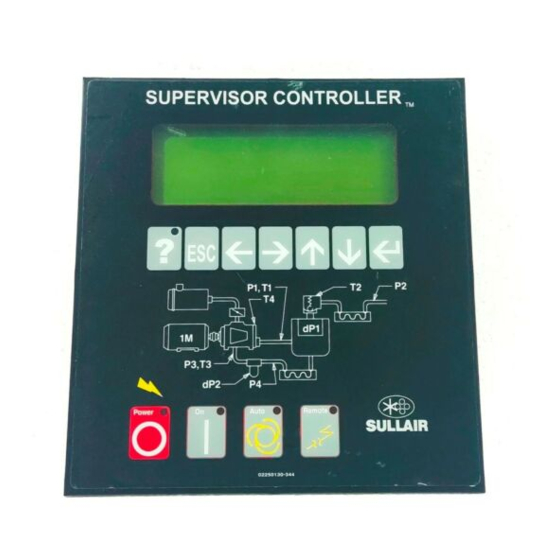
- Page 8 Section 2 SUPERVISOR DESCRIPTION Figure 2-1 Supervisor Control Panel...
-
Page 9: Supervisor Keyboard Layout
Calibration - Correction factors for pressures. 2.2 MAIN DISPLAY Test - Used by Sullair personnel for troubleshooting Line 1 - Machine state : serial communications. E-Stop - E- Stop button pressed, or auxiliary e- Factory Setup - Model settings. -
Page 10: Status- Current Pressures, Temperatures, Inputs And Outputs
Pressures - P1 through P4 depending on model. and the Drain Time is the length of the time ener- Delta pressures - dp1 through dp3 depending on gized. This does not apply to the Sullair SCD zero model. loss drain, which is not controlled or monitored by Load Hours - Hours machine has run loaded. -
Page 11: Maintenance- Preventive Maintenance Information And Timers
Section 2 SUPERVISOR DESCRIPTION number larger than zero, the machine restarts after These hours and part numbers can be changed a delay defined by this time. For example, if the using the enter and arrow keys. Restart Time is set to 10 seconds, then the machine 2.7 FAULT LOG - LOG OF PREVIOUS FAULTS will be enabled to start after 10 seconds. -
Page 12: System Display- Display Of Modes Of Machines In A Sequencing System
E - Emergency Stop ing of serial communications. M - Manual stop 2.13 FACTORY SETUP- Model settings. R - Remote stop The factory setup display is used by Sullair person- B - Standby nel to initially set up the machine. The following val-... - Page 13 Section 2 SUPERVISOR DESCRIPTION ues reflect the machine configuration. Load Hours - Hours machine was running and loaded. Model - Model number of machine. Run Hours - Hours machine was running loaded Cooling - Air or Water. and unloaded. Press Trans - Pressure transducer range 200, 250, Load Cycles - Number of load/unload cycles.
- Page 14 Section 2 SUPERVISOR DESCRIPTION Table 2-1 Supervisor Controller Menu Tree...
-
Page 15: Motor Rotation Direction Check
Section 3 START-UP PROCEDURES 3.1 MOTOR ROTATION DIRECTION CHECK 4. Start the compressor in the desired operating After the electrical wiring has been done, it is nec- mode essary to check the direction of the motor rotation. 5. Slowly open the shut-off valve to the service line. With the control system in MANUAL mode, press 6. - Page 16 NOTES...
-
Page 17: Troubleshooting Introduction
Sullair described problems. However, DO NOT assume Distributor or the Sullair Corporation factory Service that these are the only problems that may occur. All Department. available data concerning the trouble should be systematically analyzed before undertaking any 4.2 TROUBLESHOOTING GUIDE- SUPERVISOR CONTROLLER... - Page 18 40°F (4°C). ALWAYS Sensor failure, check sensor, wiring and tubing. ALWAYS Oil Pressure Low Oil pump failure, consult Sullair P3 Oil Pressure Low, service department. dP3 Oil Pressure Low ALWAYS Oil filter clogged; replace oil filter. FLOODED...
- Page 19 Section 4 TROUBLESHOOTING 4.2 TROUBLESHOOTING GUIDE- SUPERVISOR CONTROLLER (CONTINUED) MESSAGE MODEL ENABLE PROBABLE CAUSE REMEDY ALWAYS Sump Pressure High (Poppet, FLOODED Solenoid valves, check operation P1 Sump Pressure High Sullicon, Spiral or Blowdown, or and wiring. (CONTINUED) Pneumatic Valve Failed) (cont.) ALWAYS Pressure regulator, check adjust- ment and operation.
- Page 20 Section 4 TROUBLESHOOTING Table 4-1A Analog Alarms (Flooded Screw Compressors Less Than 200 psi) Start Sensor Type Limit Delay Delay Check (*) Comment High Inhibit At Start High sump psi at start Low Fault When Running Immediate Fault High Fault Constantly Sensor failure fault High Fault...
- Page 21 Section 4 TROUBLESHOOTING Table 4-1B Analog Alarms (LS-16T, LS-20T and LS-20TS Compressors) Start Sensor Type Limit Delay Delay Check (*) Comment Low Fault When Running Immediate Fault High Inhibit At Start High sump psi at start High Fault 500** Constantly Sensor failure fault High Fault 500**...
- Page 22 Section 4 TROUBLESHOOTING Table 4-2 Parameters Type Enable Default Display Text Comment Setup Always Press Trans 200,250,500, 750 Setup X200 P1 Max 250psi transducer Setup X250 P1 Max 200psi transducer Setup X500 P1 Max 500psi transducer Setup X750 P1 Max 750psi transducer Setup Always...
-
Page 23: Machine Behavior After A Power Outage
Section 4 TROUBLESHOOTING 4.3 MACHINE BEHAVIOR AFTER A POWER OUT- the Remote Start/Stop input. See previous table for column descriptions. Condition: Machine was in a running or ready con- dition when power was lost. Table 4-3 below describes how a machine behaves after a power up under various conditions if the Restart timer is the Sequencing Mode parameter must be set to Remote to enable Remote Start/Stop input. - Page 24 NOTES...
-
Page 25: Wiring Diagram- Supervisor Communication Module
Section 5 WIRING SCHEMATIC DIAGRAMS 5.1 WIRING DIAGRAM- SUPERVISOR COMMUNICATION MODULE 02250131-248R01... -
Page 26: Wiring Diagram- Supervisor Control
Section 5 WIRING SCHEMATIC DIAGRAMS 5.2 WIRING DIAGRAM- SUPERVISOR CONTROL 02250132-198R00... -
Page 27: Safety
6.2 OVERVIEW this voltage is extremely dangerous and may cause death or severe injury. The Sullair VSD drive application is custom designed for operation of air compressors. All nec- essary control functions are performed through the Supervisor keypad. The drive functions as a mod- Before opening the variable speed drive covers: ule on the Supervisor communications bus. -
Page 28: Supervisor Display And Menus
OSHA, National Electrical Code, and/or any other appli- cable State, Federal and local electrical codes concerning isolation switches, fused disconnects, etc. Sullair provides a wiring diagram for use by the installer. Customer must provide electrical supply power disconnect within sight of machine. -
Page 29: Control Parameters
Section 6 VARIABLE SPEED DRIVE KWH - Running total of energy used in kilowatt- (spiral valve) control systems. hours. Reset Load Est. - This resets the "Recent Usage" Cost - Running total of cost of operation. values to zero in the VSD Status calculations. This functions similarly to a trip odometer in a car. -
Page 30: Startup Of New Compressor Package
Section 6 VARIABLE SPEED DRIVE Motor FLA - The motor's rated full load amps at • Visually check all power and controls con- nominal HP (I) nections to the drive to ensure that no dam- age has occurred. Motor SF - The motor's nameplate service factor 3. - Page 31 Charging Switch The charging switch was open when the Reset the fault and restart. START command was been given due to: Should the fault re-occur, contact Sullair service. • faulty operation • component failure Emergency stop An Emergency stop signal was received from...
- Page 32 Set Supervisor VSD to "Serial". board has failed If installation is correct contact Sullair service. Slot fault Defective option board or slot Check that the board is properly installed and seated in slot. If the installation is correct, contact...
- Page 33 NOTES...
- Page 34 WORLDWIDE SALES AND SERVICE SULLAIR ASIA, LTD. SULLAIR EUROPE, S.A. Sullair Road, No. 1 Zone Des Granges BP 82 Chiwan, Shekou 42602 Montbrison Cedex, France Shenzhen, Guangdong PRV. Telephone: 33-477968470 PRC POST CODE 518068 Fax: 33-477968499 Telephone: 755-6851686 www.sullaireurope.com Fax: 755-6853473 www.sullair-asia.com...
Need help?
Do you have a question about the SUPERVISOR CONTROLLER Series and is the answer not in the manual?
Questions and answers