
Subscribe to Our Youtube Channel
Related Manuals for SMA SUNNY CENTRAL 500CP-US/CA


Summary of Contents for SMA SUNNY CENTRAL 500CP-US/CA
- Page 1 Maintenance Manual SUNNY CENTRAL 500CP-US/CA / 500CP-US/CA 600V / 630CP-US/CA / 720CP-US/CA / 750CP-US/CA / 800CP-US/CA / 850CP-US/CA / 900CP-US/CA SCCP-US-WH-US_en-31 | 98-123900.01 | Version 3.1 AMERICAN ENGLISH...
- Page 2 All such warranties are expressly disclaimed. Neither SMA America, LLC nor its distributors or dealers nor SMA Solar Technology Canada Inc. nor its distributors or dealers shall be liable for any indirect, incidental, or consequential damages under any circumstances.
- Page 3 A warning describes a hazard to equipment or personnel. It calls attention to a procedure or practice, which, if not correctly performed or adhered to, could result in damage to or destruction of part or all of the SMA equipment and/or other equipment connected to the SMA equipment or personal injury.
- Page 4 All installations must conform with the laws, regulations, codes and standards applicable in the jurisdiction of installation. SMA assumes no responsibility for the compliance or noncompliance with such laws or codes in connection with the installation of the product.
-
Page 5: Table Of Contents
SMA America, LLC Table of Contents Table of Contents Information on this Document........... . . 7 1.1 Validity . - Page 6 SMA America, LLC Table of Contents 7.11 Checking the Latches, Door Stops and Hinges..........42 7.12 Checking the Switch Cabinet for Corrosion .
-
Page 7: Information On This Document
29 CFR, Chapter XVII, Part 1910 (OSHA), NEC, and NFPA 70E, and possess all the necessary background for averting danger. There must be written documentation of their training. 1.3 Additional Information You will find further information in the download area of www.SMA-America.com. Information Document type... -
Page 8: Typographies
1.6 Nomenclature The following nomenclature is used in this document: Complete designation Designation in this document SMA America Production, LLC SMA Solar Technology Canada Inc. Sunny Central of the CP-US production series Sunny Central or inverter Sunny Central Communication Controller SC-COM... -
Page 9: Abbreviations
SMA America, LLC 1 Information on this Document 1.7 Abbreviations In this document, abbreviations are used at certain points. In the following table, you will find the full designation and an explanation, where applicable. Abbreviations Designation Explanation Alternating Current Direct Current... -
Page 10: Safety
2 Safety SMA America, LLC 2 Safety In this section, you will find general safety precautions which you must observe whenever working on the Sunny Central inverter. Pay special attention to these sections to avoid personal injury and property damage. - Page 11 Unauthorized persons may not operate the inverter and must keep at a distance from the inverter. No reconstruction, modification or installation of additional components may be carried out on the inverter without the express consent of SMA America, LLC. The inverter must not be operated with its doors open.
-
Page 12: Safety Precautions
2 Safety SMA America, LLC 2.2 Safety Precautions This section contains safety precautions that must be observed at all times when working on or with the product. To prevent personal injury or property damage and to ensure long-term operation of the product, read this section carefully and follow all safety precautions at all times. - Page 13 SMA America, LLC 2 Safety Danger to life from electric shock if the inverter is damaged Operating a damaged inverter can lead to hazardous situations that result in death or serious injuries due to electric shock. • Only use the inverter when it is technically faultless and in an operationally safe state.
- Page 14 2 Safety SMA America, LLC Risk of burns due to hot components Some components of the inverter can become very hot during operation. Touching these components can result in burn injuries. • Observe the safety warnings on the components. • During operation, do not touch any components marked with such messages.
-
Page 15: Personal Protective Equipment
Hazard Risk Category 2 protective equipment required In accordance to NFPA 70E, an arc flash hazard risk analysis has been performed by SMA, and appropriate Arc Flash Hazard labels stating the required Personal Protective Equipment (PPE) for exposed, energized interaction with the equipment, are installed. -
Page 16: Product Description
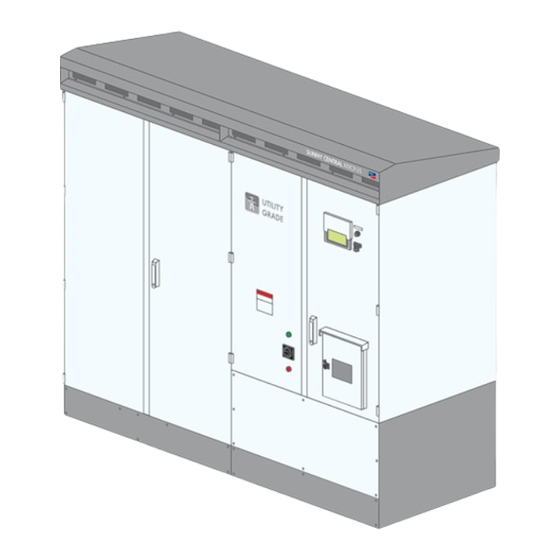
3 Product Description SMA America, LLC 3 Product Description This section will give you an overview of the inverter and its components. 3.1 Plant Overview The inverter converts the direct current generated in the PV modules into grid-compliant alternating current. - Page 17 SMA America, LLC 3 Product Description Position Designation PV modules String-Combiner Inverter with integrated AC Disconnect DC Disconnect Unit External transformer Utility grid Inverter with External AC Disconnect and External DC Disconnect As an option, the internal AC circuit breaker of the inverter can be mounted externally.
-
Page 18: Design Of The Inverter
You will require the information on the type label to use the product safely and when seeking customer support from the SMA Service Line. The information listed on the type label includes the following information: •... -
Page 19: Symbols On The Product
Schematic diagrams in PDF format contain jump marks. By double clicking a jump mark, the display will change to the corresponding current path or the referenced place in the equipment list. SMA recommends using schematic diagrams in PDF format during troubleshooting. The schematic diagrams in PDF format are available on request. Contact the SMA Service Line. -
Page 20: Information On Maintenance
The plant location and ambient conditions influence the maintenance intervals. • If the inverter is installed in adverse ambient conditions, SMA recommends a monthly inspection in order to determine the need for maintenance. The maintenance intervals are to be shortened depending on the determined maintenance requirements. -
Page 21: Spare Parts
Spare parts can be identified via their reference designation and the circuit diagram. The spare-parts list includes the article number of each spare part. For information on a specific article number, contact the SMA Service Line. 5 Maintenance with DC, AC and Control Voltage Present 5.1 Reading the Replacement Interval Meter... - Page 22 ☑ The DC contactor is switched off. ✖ The DC contactor does not switch off? • Contact the SMA Service Line. 4. Check the bolted connections of the DC contactor for discolorations and damages. If the cable entries are discolored or damaged, contact us (see Section 10, page 50).
-
Page 23: Checking The Ac Circuit Breaker
☑ The DC contactor is switched on. ✖ The DC contactor does not switch on? • Contact the SMA Service Line. 9. Switch the inverter to Stop. 10. Test the switching process three times. Check three times whether the DC contactor has switched. - Page 24 2. Use the testing device to check whether the AC circuit breaker is ready for operation (instructions for testing are included in the documentation of the testing device). If a fault occurs during the test, contact the SMA Service Line. 3. Close the doors of the interface cabinet.
-
Page 25: Disconnecting The Inverter
SMA America, LLC 6 Disconnecting the Inverter 6 Disconnecting the Inverter Prior to performing any work on the inverter, disconnect it from any voltage sources as described in this section. Danger to life from electric shock due to live voltage High voltages are present in the live components of the inverter. - Page 26 Hazard Risk Category 2 protective equipment required In accordance to NFPA 70E, an arc flash hazard risk analysis has been performed by SMA, and appropriate Arc Flash Hazard labels stating the required Personal Protective Equipment (PPE) for exposed, energized interaction with the equipment, are installed.
- Page 27 SMA America, LLC 6 Disconnecting the Inverter 3. Secure the DC Switch in the door against accidental reconnection using a padlock. 4. Wait 15 minutes until the inverter capacitors have discharged completely. 5. Externally disconnect the AC voltage of the MV transformer.
-
Page 28: Maintenance In Disconnected State
7 Maintenance in Disconnected State SMA America, LLC 14. Disconnect the circuit breaker of the 24 V circuits. 15. Open the test and disconnect terminals. 16. Ensure that all poles are free of voltage. 17. Ground and short-circuit the inverter. -
Page 29: Removing The Panels
SMA America, LLC 7 Maintenance in Disconnected State 7.2 Removing the Panels Grounding straps at the kick plates The panels are connected to the inverter via grounding straps. Procedure: Danger to life due to electric shock or electric arc by touching live components •... -
Page 30: Cleaning The Air Duct And Insect Screens
7 Maintenance in Disconnected State SMA America, LLC Procedure: Danger to life due to electric shock or electric arc by touching live components • Disconnect the inverter and wait 15 minutes until the capacitors have discharged completely (see Section 6). - Page 31 SMA America, LLC 7 Maintenance in Disconnected State Procedure: Danger to life due to electric shock or electric arc by touching live components • Disconnect the inverter and wait 15 minutes until the capacitors have discharged completely (see Section 6).
- Page 32 7 Maintenance in Disconnected State SMA America, LLC 8. Check the insect screens for visible damage. ☑ The insect screens are not damaged. ✖ Are the insect screens damaged? • Replace the damaged insect screens. 9. Insert the right-hand insect screen.
-
Page 33: Cleaning The Interior
If the fuses or tension springs are discolored or show signs of wear, replace them. 5. Check the insulation and terminals for discoloration and signs of wear. If the insulation or terminals are discolored or show signs of wear, contact the SMA Service Line. 6. Close the interface cabinet. -
Page 34: Checking The Surge Arrester
7 Maintenance in Disconnected State SMA America, LLC 7.7 Checking the Surge Arrester Figure 7: Position of the surge arrester Position Designation Ready indicator of the surge arrester Additionally required maintenance material (not included in the scope of delivery): ☐ A testing device approved by the manufacturer of the surge arrester (e.g. -
Page 35: Checking The Screw Connection Of The Power Cabling
Damage to screw connections from over-tightening • Only tighten loose connections applying the prescribed torque. Torque specifications are shown in the installation manual of the inverter. Contact the SMA Service Line if specifications are missing. Figure 8: Position of the power cabling... - Page 36 If insulation and connections are discolored or changed, contact the SMA Service Line. 4. Check the screw connections for damage and contact elements for corrosion. If screw connections are damaged or contact elements are corroded, contact the SMA Service Line. SCCP-US-WH-US_en-31...
-
Page 37: Checking The Safety Labels
SMA America, LLC 7 Maintenance in Disconnected State 7.9 Checking the Safety Labels 7.9.1 Inverter without Integrated DC Switch Figure 9: Safety messages on the Sunny Central Position SMA order number Designation 86-0043464 Warning label general SC-US EN 86-430042 Warning label Arc Flash Hazard Protection... - Page 38 86-0043477 Warning label, SC US stack capacitors EN/FR * For Sunny Central 500CP-US 600V Replacing safety messages • Replace missing or damaged safety labels. These can be ordered from SMA using the SMA order number stated above. SCCP-US-WH-US_en-31 Maintenance Manual...
-
Page 39: Inverter With Integrated Dc Switch
SMA America, LLC 7 Maintenance in Disconnected State 7.9.2 Inverter with Integrated DC Switch Figure 10: Safety messages on the inverter Position SMA-Bestellnummer Bezeichnung 86-0043464 Warning label general SC-US EN 86-430042 Warning label Arc Flash Hazard Protection 86-0033325 Label "Closed" 86-00480030 Label "Photovoltaic System AC Disconnect"... - Page 40 7 Maintenance in Disconnected State SMA America, LLC Position SMA-Bestellnummer Bezeichnung 86-0033326 Warning label Electric Shock due to Live Voltage EN/ES 86-0033327 Warning label Electric Shock due to Live Voltage EN/FR 86-004300 Warning label Burn Hazard 86-0043472 Only for order option DC fuses: Warning label SC-US DC fuses...
-
Page 41: Checking The Door Seals
Procedure: Replacing warning labels Missing or damaged warning labels must be replaced. The warning labels can be ordered from SMA using the SMA order numbers listed above. Danger to life due to electric shock or electric arc by touching live components •... -
Page 42: Checking The Latches, Door Stops And Hinges
7 Maintenance in Disconnected State SMA America, LLC If seals are damaged, contact the SMA Service Line. 3. Maintain seals with talcum, petroleum jelly or wax. This prevents frost damage. 4. If the side panels are removed, check whether or not the seals in the side panels show any damage in the sealing area. -
Page 43: Mounting The Panels
SMA America, LLC 7 Maintenance in Disconnected State 2. Check surfaces for damage or corrosion. If the surfaces are damaged, repair them without delay or within three weeks at the latest. If the surfaces are corroded, repair them without delay or within three weeks at the latest. -
Page 44: Connecting The Control Voltage
8 Connecting the Control Voltage SMA America, LLC 5. Attach the panels to the inverter using a Torx screwdriver. Torque: 18 in.-lbs. to 27 in.-lbs. (2 Nm to 3 Nm). 8 Connecting the Control Voltage Electric shock due to live voltage High voltages are present in the inverter and its components. -
Page 45: Maintenance When Control Voltage Is Present
SMA America, LLC 9 Maintenance when Control Voltage is Present 3. Switch the circuit breaker of the grid monitoring on. 4. Switch on the circuit breaker of the 24 V circuits. 5. Close the test and disconnect terminals. 9 Maintenance when Control Voltage is Present 9.1 Safety... -
Page 46: Checking The Integrated Dc Switch
3. Connect the control voltage (see Section 8 "Connecting the Control Voltage", page 44). ☑ The internal fan and the inverter bridge fan start up for a short time. ✖ The internal fan and inverter bridge fan do not start? • Contact the SMA Service Line. SCCP-US-WH-US_en-31 Maintenance Manual... - Page 47 4. Open the doors of the interface cabinet. 5. Check whether the DC load-break switches are both indicating the Off position. If either of the DC load-break switches are not indicating the Off position, contact the SMA Service Line. 6. Close the doors of the interface cabinet.
-
Page 48: Checking The Heating Element, Hygrostat And Fan
9 Maintenance when Control Voltage is Present SMA America, LLC 9.3 Checking the Heating Element, Hygrostat and Fan Danger to life due to electric shock when opening the inverter cabinet There are live components behind the doors of the inverter cabinet. - Page 49 5. Check whether the heating element is beginning to radiate heat after approx. five minutes. If the heating element does not radiate heat, contact the SMA Service Line. 6. Reset the hygrostat to the initial value. Press the selector switch against the hygrostat again. The initial value of the hygrostat is included in the circuit diagram.
-
Page 50: Contact
10 Contact SMA America, LLC 10 Contact If you have technical problems concerning our products, contact the SMA Service Line. We require the following information in order to provide you with the necessary assistance: • Device type • Serial number •... - Page 52 SMA Solar Technology www.SMA-Solar.com...
Need help?
Do you have a question about the SUNNY CENTRAL 500CP-US/CA and is the answer not in the manual?
Questions and answers