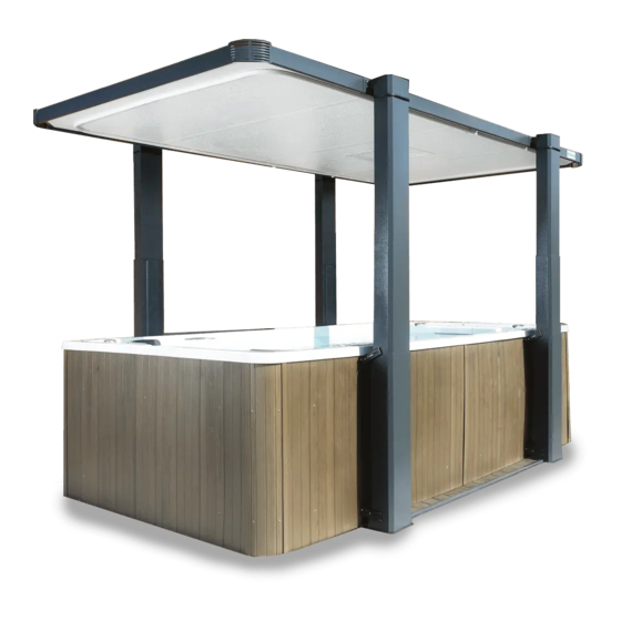
COVANA LEGEND Installation Manual
Hide thumbs
Also See for LEGEND:
- Owner's manual (97 pages) ,
- Installation manual (66 pages) ,
- User manual (28 pages)
Table of Contents
Advertisement
Advertisement
Table of Contents

Related Manuals for COVANA LEGEND


Summary of Contents for COVANA LEGEND
- Page 1 2019 Revision 2 2019-06-13 TABLE OF CONTENTS INSTALLATION MANUAL C.A. 232868...
-
Page 2: Table Of Contents
Avoiding the risk of electrocution ..........................43 AC Control box ..............................44 Optional Emergency battery backup ........................44 Battery and solar panel ............................45 Testing the COVANA cover ..........................46 Wiper brackets installation ............................47 Seal application ..............................48 Upper limit reset of posts ............................50 APPENDIX ................................51 TECHNICAL SPECIFICATIONS ..........................54... - Page 3 Battery charging (For Battery-operated models and Emergency-Battery backup only) ........58 TROUBLESHOOTING .............................59 INSTALLATION CHECKLIST (Customer copy) ....................61 INSTALLATION CHECKLIST (Installer copy) .......................63 INSTALLATION MANUAL TABLE OF CONTENTS...
-
Page 4: Safety
IMPORTANT SAFETY INSTRUCTIONS during use. Never use any type of pressure washer or buffer to clean any surface of the COVANA cover. This SAVE THESE SAFETY INSTRUCTIONS AND could result in premature wear or damage. REVIEW THEM REGULARLY. READ AND FOLLOW ALL INSTRUCTIONS Remove the control key after operating the ... -
Page 5: Avoiding The Risk Of Electrocution
Do not roll the COVANA cover onto its side or used, or if improper digging occurs. slide it on its side. This will damage the siding. - Page 6 COVER The COVANA cover was designed, tested and certified for the sole purpose of covering and Any modifications to the COVANA cover, such as securing a spa. Any installation that differs in mechanical, electrical or aesthetic ones, may...
-
Page 7: Labelling
LABELLING WARNING ♦ Removing any labels from the COVANA cover will void product certification. All labels should always remain visible. It is the owners’ responsibility to ensure these labels are always visible and should never be removed Key operating diagram, located on the key switch. - Page 8 Key switch warning, located on the key switch cable Electrical information, located on the key switch cable Do not step on cover label, located of end C-Channels of the COVANA cover Top label, located on I-Beams and Escape hatch opening...
-
Page 9: Glossary
Figure 1 AC control box The AC control box powers and controls the lifting mechanism of the COVANA cover. (AC-operated model only) Figure 2 Battery pack The battery pack is a sealed case where the two 12 V batteries are located. - Page 10 The control box manages the movement of the unit. (for battery-operated model only) Figure 6 Control box housing The control box contains all the electronic parts of the COVANA. (for battery-operated model only) Figure 7 Contour seal The contour seal ensures uniform contact between the cover and the swim spa.
- Page 11 Corner cover The corner cover is an aesthetic aluminum grid fixed to the corner bracket. Figure 12 Drive shaft The drive shaft transmits the power between the jack assemblies. Figure 13 Escape hatch The escape hatch is a removable panel and part of the cover. Refer to Using the escape hatch section.
- Page 12 The I to C spacer is used to prevent over tightening of the I to C connection plates. Figure 21 Key switch The key switch is used to operate the COVANA cover. Figure 22 Mount bracket arm This mount bracket arm will link the sleeves and swim spa together.
- Page 13 Post mount bracket Post mount bracket links the sleeves and posts to the cover. Dual side brackets are used for higher or lower swim spas. Dual side bracket (optional) (optional) Figure 24 Sleeve The sleeve is an aluminum case for the lifting mechanism. Figure 25 Support bracket The support bracket strengthens the joint between the center...
- Page 14 The U-frames protect the drive shaft. They are fastened to the bottom of the posts. Figure 30 Wiper bracket The wiper bracket is adhered under the I-beams. This part is required to ensure the waterproofing of the COVANA cover. Figure 31 GLOSSARY INSTALLATION MANUAL...
-
Page 15: Hardware Identification Table
HARDWARE IDENTIFICATION TABLE Quantity Visual representation Description 5/16-18 x 2” This hexagonal bolt is used for the lower U- frame assembly. 10-24 x 1/2” thread cutting screw. Used on the panel (33x for model assembly. with long support bracket approx. 42’’[1,066 mm]) #8 x 1/2”... - Page 16 #10-12 x 3/4” Screws used for anchoring the tub mount brackets. 1/4” Lock washer used for the mount brackets and sleeve assemblies. 1/4” Flat stainless steel washer used for mount brackets and cover assembly. 1/4-20 Hex nut. Used for sleeve and mount brackets assemblies.
-
Page 17: Installation Preparation
To ensure the safe use of the COVANA cover, it must The key switch must be permanently mounted be installed on a properly prepared surface. It is and located 5’... -
Page 18: Foundation Preparation
level surface, such as an engineered wood deck or a concrete slab. Each of the four jacks of the COVANA cover must be properly fastened to the swim spa frame. It is the installer’s responsibility to ensure the COVANA cover is properly fastened and in a safe 112”... -
Page 19: Installation
Stepladder CAUTION The COVANA cover should be installed by a certified COVANA installer. Having the COVANA cover installed by someone who is not certified will void the warranty. Ask your local COVANA dealer for information on certified installers. - Page 20 9) Remove all boxes above the jack box, place them in a safe place (Figure 36). Note: All the hardware, brackets and other parts are located in these boxes. Figure 36 10) Unscrew the Robertson #8-10 x 1.5” screws holding the jack box – four screws per side: two screws at the top, two screws at the bottom.
- Page 21 11) With the help of another person, remove the jack box from the crate and place it in a safe place. (Figure 38) WARNING Carefully slide the jack box out. Some parts can be damaged if the jack box is pulled out too roughly.
- Page 22 17) With the help of another person, lay the crate horizontally on its back. There should be one person on each side of the crate. (Figure 42) WARNING The crate is heavy; you may require a third person for rotating the crate. Figure 42 18) Unscrew the 11 Robertson #8-10 x 1.5”...
-
Page 23: Cover Assembly
Cover assembly WARNING Foams Before assembling, keep in mind not to overtighten bolts. Power tools must not be used. The bolts will break under too much torque. Note: The following figures represent the assembly of a 19’ model. The number of panels may vary depending on the actual cover size you are assembling. - Page 24 4) For models ranging from 12’ to 15’, you will need I to C to install one I-beam with two short I to C Carriage spacer bolt connection plates per I-beam. (Figure 48) Use 1/4-20 x 5/8” carriage bolts, 1/4-20 nuts and ...
- Page 25 Top sticker 6) It is recommended to use a table or the shipping crate as a base to build the middle top section of the cover, and later transfer it to the swim spa Escape once it is assembled. hatch seal CAUTION If there is limited space, please follow the next ...
- Page 26 Large panel 10) Slide the large (approx. 47” x 96” (119 cm x 243 cm)) panel into the C-channels. Ensure the I- beam has slid over the panel on both the bottom and top side (Figure 54). CAUTION Ensure that the panel is pushed as far as possible ...
- Page 27 13) Align the holes of the support bracket, the post Install these mount bracket and the C-channel by hand. bolts only. Assemble them with the 1/4-20 x 1” hex drive rounded head screws (5/32” (4 mm) drive). DO NOT install the bolts on the other end of the Post mount brackets yet (Figure 57).
- Page 28 15) Use the binding blocks provided and two 50’ (15 m) ratchet straps to help you align the side holes on the other end of the assembly (Figure 60 and Figure 61). Straps CAUTION Use cardboard or non-abrasive material under ...
- Page 29 17) Assemble the support bracket on the other end of Support the cover (Figure 62). bracket 18) Attach the post mount bracket and the support Install these bracket with the 1/4-20 x 1” hex drive rounded bolts. head screws (5/32” (4 mm) drive) (63.9 in-lbs) (Figure 62).
- Page 30 22) Carefully position the assembled center section Short C-channel of the cover onto the swim spa. Try to align the cover as best as possible. CAUTION Holes Failure to gently position the cover onto the swim Support spa could result in scratching the acrylic of the bracket spa or damaging the cover.
- Page 31 C-Channel For models 12’ to 15’ only, go to step 29. Rectangular panel 26) Slide in one of the remaining rectangular panels into the C-channels. (Figure 73) CAUTION It is very important to check if the I-beams have locked in properly into the foam panels. If you have a color panel, make sure the colored ...
- Page 32 31) Repeat steps 26 to 30 on the other side. Inwards to cover Corner 32) If necessary, use the ratchet straps to properly bracket lock in the foam panels. CAUTION Use cardboard or a non-abrasive material to protect panels while using ratchet straps. WARNING Do not over tighten the straps.
- Page 33 37) Fasten the Robertson sheet metal #8 x 3/4” #8 Screws screws that hold the side C-channel (Figure 78). Note: If the gap between the corner bracket and side C-channel is too large, try bringing the two parts closer by hand before fully screwing. Side C-channel WARNING Do not overtighten the screws as they might...
- Page 34 39) Use the provided 5/32” drill bit to drill the holes on the top and bottom of the support bracket (four Holes for drilling holes per bracket) (Figure 79 and 80). Use the pre-drilled holes in the support bracket as guidance.
- Page 35 All security risks such as drowning, injury or undesired entry due to an open COVANA cover without an escape hatch installed are not approved by COVANA and product certification will be void.
-
Page 36: Lifting Mechanism Assembly
MDF panels, plastic skirting or any composite siding is not approved by COVANA and is not safe for operation. Improper fastening to the swim spa’s frame can result in serious injury or even death when the cover operates. - Page 37 Non-motor jacks 4) Position the jacks in their locations. Motorized jacks should always be on the left side when looking at the swim spa. (Figure 88) NOTE: Position the non-motor jack with the bonding lug (Figure 90) on the same side where Motor jacks the control box will be installed.
- Page 38 8) Install the aluminum U-frame over the drive shaft. The U-frame will bolt on top of the post bracket of the motor and non-motor jacks. Fasten in place using the hardware provided: four hexagonal 5/16-18 x 2” bolts and 5/16-18 nylon insert locknuts.
- Page 39 13) Locate the short end of the cable, which can be identified from the metal compression connector near the end of the cable. Make the connector go through the center hole on the back of the motor jack’s base plate. Connect the cable to the motor harness tighten screws...
- Page 40 (Figure 95).) Further unscrewing is not considered safe and is not recommended by COVANA. Figure 95 Failure to follow these guidelines could cause ...
- Page 41 18) Use a level to ensure that the four posts are vertically level. Rounded 19) Attach the top mount bracket arms to the tub section mount brackets using the 1/4-20 x 1” hex drive bolt, 1/4” flat washer on the outside. Use a 1/4 lock washer and 1/4-20 nut on the inside.
- Page 42 23) Attach the top plate cover for all four posts. Use the provided Robertson #8 self-drilling screws x 1/2” (2 screws per post) (Figure 101) Top plate cover Figure 101 #8 screws 24) For all four posts, slide the all-weather seals down.
-
Page 43: Electrical Hook-Up
(GFCI) that complies with applicable local electrical codes and regulations. Install the COVANA cover in such a way that drainage directs water away from the electrical components and base mechanical components. Do not connect any auxiliary components to the ... -
Page 44: Ac Control Box
AC Control box ELECTRICAL WARNING The charger must always be indoors, away from (for AC-operated model only. If you are installing a battery- operated model, skip to ‘’battery and solar panel’’ section’) water. Damage, injury or death may occur if this instruction is not followed 1) Place the pre-assembled control box and its holding bracket on one of the U-frames between... -
Page 45: Battery And Solar Panel
ELECTRICAL WARNING Do not place the solar panel on the COVANA cover since the wire will hang above water and might cause electrocution. -
Page 46: Testing The Covana Cover
CAUTION This ensures the user has a clear view of the COVANA cover when operating it. Furthermore, If the COVANA cover is in an area with limited the key switch terminal should be located in a clearance, never completely lift the COVANA place where no water downpour or debris could cover while performing this test sequence. -
Page 47: Wiper Brackets Installation
Lift the cover halfway up to proceed to the next steps. The next steps are important for minimizing water intrusion. CAUTION For COVANA covers between 12’ and 15’, there will be 6 wiper brackets. For models 16’ to 20’, Back siding there will be 10 wiper brackets. -
Page 48: Seal Application
Seal application Masking tape 6) Once the COVANA cover has been fully assembled, raise the cover and remove the foam spacers and tape. Lower the cover and walk around the entire perimeter of the spa, observing where the inside surface of the cover will make contact with the spa. - Page 49 The rubber seal should underside of the cover. To apply pressure to the not be overheated. Do not directly heat the acrylic seal, simply push it against the COVANA cover or seal, as this may cause permanent damage. with your hands.
-
Page 50: Upper Limit Reset Of Posts
Should there be an object that will obstruct the Use the key switch to raise the cover. COVANA cover during operation, please follow the Note: Every time that the height of the cover is next steps to reset the maximum height of the cover changed, the 30-second countdown will restart. -
Page 51: Appendix
APPENDIX INSTALLATION MANUAL APPENDIX... - Page 52 TECHNICAL SPECIFICATIONS INSTALLATION MANUAL...
- Page 53 INSTALLATION MANUAL APPENDIX...
-
Page 54: Technical Specifications
TECHNICAL SPECIFICATIONS Side elevations 3.5” (8.9 cm) The travel is electronically set to 60’’ (150 cm). Add the swim spa height to the travel to have COVANA maximum your maximum height. elevation is 120” (300 cm) Swim spa wall on both sides must be flat and parallel. -
Page 55: Frame And Footprint
Frame and footprint Figure 117 INSTALLATION MANUAL TECHNICAL SPECIFICATIONS... -
Page 56: Electrical Specifications (For Ac-Operated Model)
10 A single-pole GFCI (not included) Continuous current draw 1.5 A WARNING COVANA does not allow any modifications of the electrical system. COVANA reserves the right to void the warranty if any modification is done without its specific approval. Electrical specifications... -
Page 57: Operating Limitations
Maximum weight on the cover 200 lb (90 kg) (evenly distributed) * The load specification for the LEGEND cover is a provision for environmental outcomes, typically some snow or damp leaves that could accumulate on the cover. General specifications Lifting speed 2.5”/sec (6.35 cm/s) -
Page 58: Battery Charging (For Battery-Operated Models And Emergency-Battery Backup Only)
Battery charging (For Battery-operated models and Emergency-Battery backup only) The COVANA Cover includes two 24 V DC battery packs. Since the COVANA cover operates with these batteries, it is essential to maintain and charge your battery packs Use the battery charger provided and plug it in the regular wall power outlet. (110 V North America) (220 V Europe) (Figure 118). -
Page 59: Troubleshooting
Check if any electrical cables are damaged or pinched. Check the breaker panel. COVANA cover Posts are frozen. Remove all debris from top of COVANA cover. does not raise or Cover is obstructed. Check if any posts are obstructed. - Page 60 (This page intentionally left blank, See next page) INSTALLATION MANUAL...
-
Page 61: Installation Checklist Customer Copy
□ All the parts that came with the COVANA cover were installed. □ The start-up procedure is completed. (The key sequence responds correctly and Testing the COVANA cover section is performed.) □ The all-weather seal functions properly. (The cover raises and lowers properly.) □... - Page 62 Contact your authorized COVANA dealer for all service-related issues. Made in Canada by COVANA, a division of the Canimex group www.COVANA.com PATENTED CANADA 2,532,429 US 11/162,557 UK 0515168.3 AUSTRALIA 2006200251 The information in this manual was accurate at the time of print. The manufacturer reserves the right to change or improve its product without prior notice.
-
Page 63: Installation Checklist Installer Copy
□ All the parts that came with the COVANA cover were installed. □ The start-up procedure is complete. (The key sequence responds correctly and Testing the COVANA cover section is performed.) □ The all-weather seal functions properly. (The cover raises and lowers properly.) □... - Page 64 Contact your authorized COVANA dealer for all service-related issues. Made in Canada by COVANA, a division of the Canimex group www.COVANA.com PATENTED CANADA 2,532,429 US 11/162,557 UK 0515168.3 AUSTRALIA 2006200251 The information in this manual was accurate at the time of print. The manufacturer reserves the right to change or improve its product without prior notice.
Need help?
Do you have a question about the LEGEND and is the answer not in the manual?
Questions and answers