COVANA LEGEND Installation Manual
Swim spa
Hide thumbs
Also See for LEGEND:
- Owner's manual (97 pages) ,
- Installation manual (64 pages) ,
- User manual (28 pages)
Advertisement
Available languages
Available languages
Quick Links
Download this manual
See also:
User Manual
LEGEND
Read this manual before proceeding with installation
Veuillez lire ce guide avant de procéder à l'installation
Installation Manual
Manuel d'installation
www.covana.com
Advertisement

Related Manuals for COVANA LEGEND


Summary of Contents for COVANA LEGEND
- Page 1 LEGEND Read this manual before proceeding with installation Veuillez lire ce guide avant de procéder à l'installation Installation Manual Manuel d'installation www.covana.com...
- Page 3 FRANÇAIS La version française du manuel débute à la page 31...
- Page 4 DISCONNECT OR TURN OFF ALL POWER SUPPLY BEFORE STARTING ANY INTERVENTION ON THE COVANA. WARNING RISK OF INJURY DO NOT OPERATE THE COVANA WHILE IN WATER. WARNING AVOID DROWNING RISK ENTRAPMENT POSSIBLE. FAILURE TO FOLLOW ALL INSTRUCTIONS MAY RESULT IN INJURY OR DROWNING.
- Page 5 WHEN INSTALLING AND USING THIS ELECTRICAL EQUIPMENT, BASIC SAFETY PRECAUTIONS SHOULD ALWAYS BE FOLLOWED, INCLUDING THE FOLLOWING IMPORTANT SAFETY INSTRUCTIONS WHEN USING THIS ELECTRICAL EQUIPMENT, BASIC SAFETY PRECAUTIONS SHOULD ALWAYS BE FOLLOWED, INCLUDING THE FOLLOWING: READ AND FOLLOW ALL INSTRUCTIONS. WARNING - TO REDUCE THE RISK OF INJURY, DO NOT PERMIT CHILDREN TO USE THIS PRODUCT UNLESS THEY ARE CLOSELY SUPERVISED AT ALL TIMES.
- Page 6 NOTICE THIS OPERATOR IS SPECIALLY DESIGNED TO OPERATE ONLY WITH THE COVANA LIFTING SYSTEM. UNDER NO CIRCUMSTANCES SHOULD THIS OPERATOR BE USED FOR ANY OTHER APPLICATIONS. NOTICE DISPOSAL: THIS PRODUCT MAINLY CONTAINS STEEL, COPPER (CU), ALUMINUM (AL), FIBERGLASS, & EPS.
- Page 7 DO NOT OPERATE THE UNIT UNTIL ALL MECHANICAL AND ELECTRICAL CONNECTIONS HAVE BEEN MADE. IMPORTANT ALL 4 POSTS OF THE COVANA MUST BE PROPERLY ANCHORED TO THE SWIM SPA USING THE SUPPLIED BRACKETS AT EACH POST. IMPORTANT BATTERY IS TO BE STORED INSIDE WHEN TEMPERATURES DROP BELOW -30°C (-22°F).
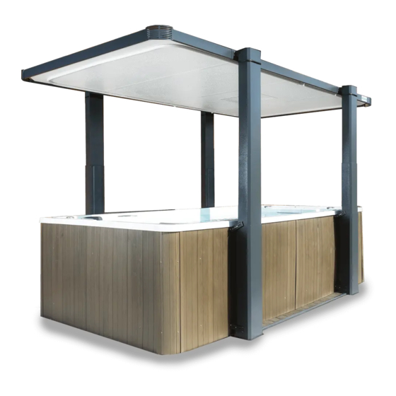
- Page 8 Just like the swim spa foundation, the Covana also requires a solid foundation. The area that the Covana sits on must be able to support at least 600 lb (272 kg) and must be leveled. All components of the Covana must be supported by the foundation.
-
Page 9: Side Elevation Dimensions
SIDE ELEVATION DIMENSIONS 3" (76 mm) The maximum elevation height depends of the height of the swim spa. Add swim spa height to the Covana travel to Covana maximum travel is determine maximum elevation. 65" (1.7 m) Example: Swim spa height + Covana travel which is 65"... -
Page 10: Frame Dimensions And Footprint
FRAME DIMENSIONS AND FOOTPRINT Motor Motor... - Page 11 ASSEMBLING THE LEGEND PART I – UNCRATING 5. Remove the front cover and place it in a safe place. REQUIRED TOOLS Scissors / Sheet metal cutter Retractable blade 7/32” Allen key knife Robertson screwdriver UNCRATING Before uncrating the unit, Make sure there is no 6.
- Page 12 ASSEMBLING THE LEGEND PART I – UNCRATING 13. Remove the seals and the foams from the crate and With a Robertson screwdriver, unscrew the screws place them in a safe place. holding the jack box. – four (4) screws per side: two (2) screws in the middle, two (2) screws in the bottom.
- Page 13 ASSEMBLING THE LEGEND PART I – UNCRATING Remove the top of the crate. Remove the fiberglass panels from the crate by lifting them up and place them in a safe place.
- Page 14 ASSEMBLY...
- Page 15 TYPICAL COVER LAYOUT FOR UNITS 12 TO 15 FT (3.66 M TO 4.6 M)
- Page 16 TYPICAL COVER LAYOUT FOR UNITS 12 TO 15 FT (3.66 M TO 4.6 M) Item Model Description number Corner outside facing Corner bracket support #8 x 1/2" pan head Phillips self tapping screw 83 3/4" (2127 mm) C-Channel (short side) 94 9/16"...
- Page 17 TYPICAL COVER LAYOUT FOR UNITS 16 TO 20 FT (4.88 M TO 6.1 M)
- Page 18 TYPICAL COVER LAYOUT FOR UNITS 16 TO 20 FT (4.88 M TO 6.1 M) Item Model Description number Corner outside facing Corner bracket support #8 x 1/2" pan head Phillips self tapping screw 83 3/4" (2127 mm) C-Channel (short side) 94 9/16"...
- Page 19 ASSEMBLING THE LEGEND PART II - ASSEMBLY 6. Slide the I-Beam in the C-Channel with the WARNING wider flat part of the I-Beam toward the bottom and the narrow portion with the lip and IMPORTANT: DO NOT over tighten seal toward the top. The bent portion of the I bolts.
- Page 20 ASSEMBLING THE LEGEND PART II - ASSEMBLY 14. Use the hammer block to ensure the panel is fully engaged in the I-beam. Gently strike the center of the block and ensure the block is continuously in contact with the panel edge.
- Page 21 ASSEMBLING THE LEGEND PART II - ASSEMBLY 22. Secure the two corner pieces using two #8 28. Using the post to cover connector bracket screws. as a guide, attach the swim spa mount brackets just under the acrylic and at the bottom of the swim spa.
- Page 22 ASSEMBLING THE LEGEND PART II - ASSEMBLY 30. Slide the drive shafts over the square shaft of 34. For both motors, slide the short end of the both motor side jacks. cable, which can be identified from the metal connector near the cable end, through the centre hole on the back of the motor jack’s base.
- Page 23 ASSEMBLING THE LEGEND PART II - ASSEMBLY 37. Use a torpedo level to make sure that the posts are completely plumb with the ground. 38. Attach the swim spa mount arms to the swim spa mount brackets using a 1" bolt, flat washer on the outside, a lock washer and nut on the inside.
- Page 24 ASSEMBLING THE LEGEND PART II - ASSEMBLY Battery Circuit breaker Key switch Motor Motor Solar panel...
- Page 25 There is a small plastic insert that should be used to keep the seal together. Note: The cover must be fully down prior to installation of the all-weather seal. 43. The Covana cover should now be raised up to ensure smooth operation.
- Page 26 ASSEMBLING THE LEGEND PART III - APPLYING THE SEAL 1. When the cover assembly is completed, 5. Test by lowering the cover to ensure that the elevate the cover using the key switch and seal makes contact along the entire perimeter.
- Page 27 ASSEMBLING THE LEGEND PART III - APPLYING THE SEAL 9. Install the water deflector. Clean and ensure dryness of the I beam before adhering the bracket in place. The vertical foam on the wiper bracket needs to align in the gap between the I beam and the C-Channel.
- Page 28 POSTS POSITION INITIALIZATION PROCEDURE This procedure must be performed in the following situations: - During the initial installation of the unit. - When the posts are not anymore at the same height. - When the posts do not detect the lower and / or upper limit(s). The procedure consists of two (2) simple steps: Control circuitry initialization to zero (0) and initialization to zero (0) of the posts.
- Page 29 POSTS POSITION INITIALIZATION PROCEDURE Using the key switch (see figure # 2), execute the following steps without interrupting the sequence during execution. Turn and hold the key switch in the lower position between 8-10 seconds. Release the key switch and immediately cycle it between 8-10 times in the lower ...
- Page 30 4. Unplug the power connector to the control box (see figure # 1 for connector location). Wait a minimum of 30 seconds before reconnecting the power to the Covana. This ...
- Page 31 OPTIONAL - SOLAR PANEL...
-
Page 32: Wiring & Schematic
WIRING & SCHEMATIC... -
Page 33: Troubleshooting
(side of the box). Battery needs to be charged. Use supplied charger to charge battery for at least 2 hours. If the Covana has the optional solar panel, ensure that it is getting adequate sunlight. The Covana will not elevate or lower Check control box connections including battery, ... - Page 34 Made in Canada by Canimex www.covana.com PATENTED CANADA 2,532,429 US 11/162,557 UK 0515168.3 AUSTRALIA 2006200251...
- Page 35 LEGEND Veuillez lire ce guide avant de procéder à l'installation Manuel d'installation www.covana.com...
- Page 36 DÉBRANCHEZ LA BATTERIE AVANT DE PROCÉDER À TOUTE INTERVENTION SUR LE COVANA. AVERTISSEMENT RISQUE DE BLESSURE NE FAITES PAS FONCTIONNER LE COVANA LORSQUE VOUS ÊTES DANS L'EAU. AVERTISSEMENT ÉVITEZ LES RISQUES DE NOYADE. RISQUE DE PRISE AU PIÈGE. LE NON RESPECT DE TOUTES LES CONSIGNES PEUT ENTRAÎNER DES BLESSURES OU LA NOYADE.
- Page 37 POUR INSTALLER ET UTILISER CET ÉQUIPEMENT ÉLECTRIQUE, DES PRÉCAUTIONS DE BASE DOIVENT TOUJOURS ÊTRE RESPECTÉES, Y COMPRIS LES SUIVANTES CONSIGNES DE SÉCURITÉ IMPORTANTES LORS DE L’UTILISATION DE CET ÉQUIPEMENT, DES PRÉCAUTIONS DE BASE DOIVENT TOUJOURS ÊTRE RESPECTÉES, Y COMPRIS LES SUIVANTES. LIRE ET SUIVRE TOUTES LES INSTRUCTIONS.
- Page 38 AVIS LE MOTEUR EST SPÉCIFIQUEMENT CONÇU POUR FONCTIONNER AVEC LE SYSTÈME DE LEVAGE DU COVANA. IL NE DEVRAIT SOUS AUCUNE CIRCONSTANCE ÊTRE UTILISÉ À D’AUTRES FINS. AVIS MISE AU REBUT : CE PRODUIT CONTIENT PRINCIPALEMENT DE L’ACIER, DU CUIVRE (CU), DE L’ALUMINIUM (AL), DES FIBRES DE VERRE ET PSE.
- Page 39 NE PAS UTILISER LE COVANA AVANT QUE TOUTES LES CONNEXIONS MÉCANIQUES ET ÉLECTRIQUES SOIENT EFFECTUÉES. IMPORTANT TOUS LES POTEAUX DU COVANA DOIVENT ÊTRE CORRECTEMENT FIXÉS AU SPA DE NAGE EN INSTALLANT LES SUPPORTS FOURNIS À CHAQUE MONTANT. IMPORTANT CONSERVEZ LA BATTERIE À L'INTÉRIEUR LORSQUE LA TEMPÉRATURE CHUTE...
- Page 40 Tout comme pour un spa, la fondation du Covana se doit d’être solide. L'emplacement où le Covana est placé doit pouvoir supporter au minimum 600 lb (272 kg) et être de niveau. Tous les composants du Covana doivent être supportés par la fondation.
- Page 41 65 po (1,6 m) Exemple : Hauteur du spa de nage + hauteur de déplacement du Covana qui est 65 po (1,6 m) = élévation totale. La hauteur du spa de nage varie mais doit être dans la plage suivante : Minimum de 49 po (1,24 m) Maximum de 62 po (1,57 m) environ.
- Page 42 DIMENSION DU CADRE ET DE LA SURFACE AU SOL Moteur Moteur...
- Page 43 Si vous découvrez des dommages, veuillez contacter le 6. Retirez la feuille de protection qui recouvre les pièces service à la clientèle de Covana au 1 (877) 278- à l’intérieur du caisson. 8010. 7. Utilisez le tourne vis Robertson pour dévisser les deux Mettez le Covana en position verticale.
- Page 44 ASSEMBLAGE DU LEGEND ÉTAPE 1 – DÉBALLAGE 13. Retirez le joint d’étanchéité et les rectangles de Utilisez le tournevis Robertson pour dévisser les vis mousse de l’intérieur du caisson et les déposez-les qui retiennent le support des quatre (4) poteaux –...
- Page 45 ASSEMBLAGE DU LEGEND ÉTAPE 1 – DÉBALLAGE Retirez le dessus du caisson. Retirez les panneaux du couvecle du caisson et déposez-les dans un endroit sécuritaire.
- Page 46 ASSEMBLAGE...
- Page 47 AGENCEMENT TYPIQUE DU COUVERCLE POUR LES MODÈLES DE 12 À 15 PIEDS (3,66 M À 4,6 M)
- Page 48 AGENCEMENT TYPIQUE DU COUVERCLE POUR LES MODÈLES DE 12 À 15 PIEDS (3,66 M À 4,6 M) N° de Modèle Description Qté la pièce Tous Coin faisant face à l'extérieur Tous Support de coin Tous Vis autotaraudeuse à tête Phillips cylindrique n°8 x 1/2 po Tous Profilé...
- Page 49 AGENCEMENT TYPIQUE DU COUVERCLE POUR LES MODÈLES DE 16 À 20 PIEDS (4,88 M À 6,1 M)
- Page 50 AGENCEMENT TYPIQUE DU COUVERCLE POUR LES MODÈLES DE 16 À 20 PIEDS (4,88 M À 6,1 M) N° Modèle Description Qté de la pièce Tous Coin faisant face à l'extérieur Tous Support de coin Tous Vis autotaraudeuse à tête Phillips cylindrique n°8 x 1/2 po Tous Profilé...
- Page 51 ASSEMBLAGE DU LEGEND ÉTAPE 2 - ASSEMBLAGE 5. Pré-assemblez tous les raccords entre les AVERTISSEMENT profilés en I et en C comme illustrés. Placez du ruban adhésif sur la tête des boulons de IMPORTANT: NE SERREZ PAS TROP les 1/4 po x 5/8 po (6 mm x 16 mm) pour boulons.
- Page 52 ASSEMBLAGE DU LEGEND ÉTAPE 2 - ASSEMBLAGE 8. Sur deux extrémités sections 12. Déplacez la section centrale du couvercle centrales du couvercle, installez le profilé en I sur le spa de nage. avec le long support I à C. Pour vous aider à...
- Page 53 ASSEMBLAGE DU LEGEND ÉTAPE 2 - ASSEMBLAGE 28. Utilisez le support du couvercle comme un 22. Fixez les deux pièces de coin en place à guide et fixez les pattes de fixation du spa l'aide de deux vis n °...
- Page 54 ASSEMBLAGE DU LEGEND ÉTAPE 2 - ASSEMBLAGE 30. Glissez les arbres d'entraînement sur l'axe 34. Pour chacun des deux moteurs, glissez la carré des deux vérins motorisés latéraux. partie courte du câble, identifiée par le connecteur métallique à l’extrémité du câble, dans le trou au centre de la partie...
- Page 55 ASSEMBLAGE DU LEGEND ÉTAPE 2 - ASSEMBLAGE 37. Utilisez un laser automatique en métal pour vous assurer que les montants sont parfaitement à l'aplomb du sol. 38. Fixez les bras de fixation du spa de nage aux pattes de fixation du spa de nage à...
- Page 56 ASSEMBLAGE DU LEGEND ÉTAPE 2 - ASSEMBLAGE Batterie Disjoncteur Interrupteur à clé Moteur Moteur Panneau solaire...
- Page 57 ASSEMBLAGE DU LEGEND ÉTAPE 2 - ASSEMBLAGE 40. Pour les modèles équipés d'un panneau 44. Une fois le couvercle relevé, vérifiez la solaire, installez le panneau solaire à l'aide position de la trappe d'évacuation. Elle de petites vis n°8. Cette procédure doit être devrait se présenter comme illustrée.
- Page 58 ASSEMBLAGE DU LEGEND ÉTAPE 3 - JOINT D’ÉTANCHÉITÉ 1. Une fois l'assemblage du couvercle terminé, 5. Essais : Abaissez à nouveau le couvercle pour élevez-le à l'aide de l'interrupteur à clé, puis vous assurer que le joint touche bien le retirez les cales en mousse.
- Page 59 ASSEMBLAGE DU LEGEND ÉTAPE 3 - JOINT D’ÉTANCHÉITÉ 9. Installez le déflecteur d’eau. Nettoyez et veillez à ce que le profilé en I soit bien sec avant de faire adhérer le déflecteur en place. La mousse verticale sur le déflecteur doit être alignée dans l'espace entre les profilés en I et...
- Page 60 PROCÉDURE D'INITIALISATION DE LA POSITION DES MONTANTS Cette procédure doit être exécutée dans les situations suivantes : – Lors de l'installation initiale. – Lorsque les montants ne sont plus à la même hauteur. – Quand les montants ne détectent pas les limites supérieures et/ou inférieures. La procédure consiste en deux (2) étapes simples : Initialisation du circuit de contrôle à...
- Page 61 PROCÉDURE D'INITIALISATION DE LA POSITION DES MONTANTS À l'aide de l'interrupteur à clé (voir Figure 2), exécutez les étapes suivantes sans interrompre la séquence pendant l'exécution. Tournez et maintenez l'interrupteur à clé dans la position du bas pendant 8 à 10 ...
- Page 62 Débranchez le connecteur d'alimentation au boîtier de commande (reportez-vous à la Figure 1 pour l'emplacement de connecteur). Attendez au moins 30 secondes avant de reconnecter l'alimentation au Covana. L'initialisation des circuits de contrôle, du réglage de la hauteur des montants, du...
- Page 63 OPTION - PANNEAU SOLAIRE...
- Page 64 CÂBLAGE & SCHÉMA...
-
Page 65: Guide De Dépannage
La batterie a besoin d'être rechargée. Utilisez le chargeur fourni pour recharger la batterie pendant au moins 2 heures. Si le LEGEND est équipé d'un panneau solaire en option, assurez-vous qu'il reçoit suffisamment de lumière du soleil. Le LEGEND ne se lève ou ne s'abaisse Vérifiez les branchements du boîtier de commande, y com-... - Page 66 Fabriqué au Canada par Canimex www.covana.com BREVETÉ CANADA 2,532,429 US 11/162,557 R-U. 0515168.3 AUSTRALIE 2006200251...
Need help?
Do you have a question about the LEGEND and is the answer not in the manual?
Questions and answers