
Related Manuals for FlowLine FloaTek LV55 Series


Summary of Contents for FlowLine FloaTek LV55 Series
- Page 1 FloaTek™ Float Level Transmitter LV55 Series Manual Flowline Inc. 10500 Humbolt Street Los Alamitos, CA 90720 Tel: (562) 598‐3015 Fax: (562) 431‐8507 www.flowline.com Rev B1 MN201345 1 of 8 ...
-
Page 2: Table Of Contents
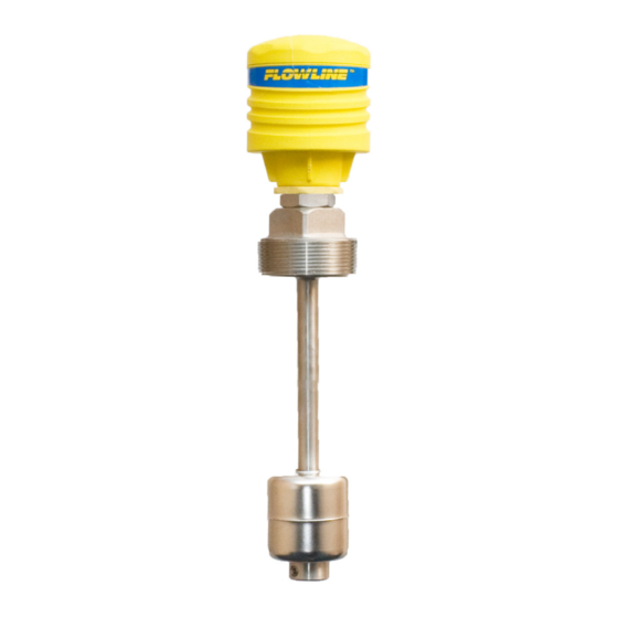
INTRODUCTION / TABLE OF CONTENTS Step One The general‐purpose float level transmitter provides continuous level measurement up to 6.5’ (2m) with a 4‐ 20 mA signal output, and is factory configured to your selected dimension. This stainless steel liquid level sensor is well suited for high temperature or pressure tank level applications with relatively clean liquids such as water, diluted chemicals and light weight oils. Application examples include boilers and process vessels. Features High pressure or temperature level measurement up to 6.5’ (2m) Rugged 316 Stainless Steel float guide and process mounting plug Assembled to your guide length and measurement span dimensions Polypropylene junction box rated NEMA 4X with ½” conduit port and terminal strip Table of Contents Specifications .............................. 3 Dimensions .............................. 3 Safety Precautions ............................ 4 ... -
Page 3: Specifications
SPECIFICATIONS / DIMENSIONS Step Two Range: 12” to 6.5’ (30cm to 2m) Preset stem lengths: 16” (0.406m), 24” (0.610m), 32” (0.813m), 36” (0.914m), 42” (1.067m) or 48” (1.219m) Resolution: ¼” Configuration: None, fixed span Orientation: ± 30° from vertical Specific gravity: 0.55 minimum Supply voltage: 10 to 30 VDC Loop resistance: 600 Ohms @ 24 VDC Signal Output: 4‐20 mA, two‐wire Process Temp.: ‐40°C to 85°C ‐40°F to 185°F Ambient Temp.: ‐40°C to 140°C ‐40°F to 60°F Pressure: 200 psi (13.8 bar) Enclosure rating: NEMA 4X (IP65) Encl. material: PP, UL94VO Conduit entrance: Single, ½” NPT ... -
Page 4: Safety Precautions
About this Manual: PLEASE READ THE ENTIRE QUICK START PRIOR TO INSTALLING OR USING THIS PRODUCT. This manual includes information on the LV55 Series Float Level Transmitter from FLOWLINE, Inc. Please refer to the part number located on the switch label to verify the exact model configuration, which you have purchased. User’s Responsibility for Safety: FLOWLINE, Inc. manufactures a broad range of level sensing technologies. While each of these sensors is designed to operate in a wide variety of applications, it is the user’s responsibility to select a sensor model that is appropriate for the application, install it properly, perform tests of the installed system, and maintain all components. The failure to do so could result in ... -
Page 5: Installation
INSTALLATION Step Four FloaTek™ level transmitter is an in‐tank system. LV55 series may be installed through the top wall of any tank or flange, using a standard 2” NPT tank adapter or blind flange. If the top is not available, Flowline’s side mount bracket, LM50, enables LV55 series to be installed directly to the side wall or lip of the tank. Tank Adapter: Flange Mounting: Side Mount Bracket: side wall installation shown Installation Tip 1. Float level transmitter should be installed rigidly so the float is free to move as the liquid level changes. 2. Float level transmitter should be mounted in a tank area free of severe turbulence or protected from such turbulence by appropriate and adequate slosh shields. ... -
Page 6: Wiring
WIRING Step Five Electrical Interface: Use the Red wire as the (+) and the Black wire as the (‐). Generic Loop Generic PLC DataView™ LI55 Series Powered Display Level Controller DataPoint™ Series Commander™ Multi‐Tank DataLoop™ LI23 Series Level Controller Level Controller Level Indicator Testing the installation Verify proper wiring, power supply and loop resistance. If transmitter is not functioning properly, isolate the transmitter from the system and wire as shown below. Multimeter should read 4 mA with float at the bottom and 20 mA with float at the top of ... -
Page 7: Maintenance
Cautions FLOWLINE, Inc. manufactures a wide range of liquid level switches and technologies. While each of these switches are designed to operate in a wide variety of applications, it is the user's responsibility to select a switch model that is appropriate for the application, install it properly, perform tests of the installed system, ... -
Page 8: Warranty, Returns And Limitations
WARRANTY, RETURNS AND LIMITAITONS Step Seven Warranty Flowline warrants to the original purchaser of its products that such products will be free from defects in material and workmanship under normal use and service in accordance with instructions furnished by Flowline for a period of two years from the date of manufacture of such products. Flowline's obligation under this ...
Need help?
Do you have a question about the FloaTek LV55 Series and is the answer not in the manual?
Questions and answers