
Related Manuals for Teufel KnieAgil Series


Summary of Contents for Teufel KnieAgil Series
- Page 1 Gebrauchsanweisung KnieAgil®-Gelenke User Manual WLD31/ WLD31s/ LD31 P44c PS21 PF50 PSB60 www.teufel-international.com...
-
Page 2: Table Of Contents
KnieAgil®-Gelenke Gebrauchsanweisung S20 Inhalt Beschreibung KA.S20 In dieser Gebrauchsanleitung sind fol gende KnieAgil®Gelenke berücksichtigt und auf den genannten Seiten zu finden: Bitte beachten Sie die Sicherheits- hinweise für alle Gelenke! KA.S20 KA.L30 KA.LD31 KA.WLD31 KA.WLD31s Das KnieAgil® S20 ist ein monozen tri KA.SL2 sches Bremsgelenk mit belastungsab... -
Page 3: Bitte Beachten Sie Die Sicherheits
KnieAgil®-Gelenke Gebrauchsanweisung S20 Technische Angaben REF/Größen Produkt Gesamtlänge, total 75 mm Gewicht (inkl. Adaption) 533 g KA.S20 KnieAgil® S 20 Max. Flexion 140 ° Indikation Lieferumfang Produkt Aktivitätsgrad: 1 + 2 KA.S20 KnieAgil® S 20 90.395.093.01 Gebrauchsanweisung Höchstbelastung: 125 kg Zubehör Die Höchstbelastung ergibt sich aus der Summe von Körpergewicht,... - Page 4 KnieAgil®-Gelenke Gebrauchsanweisung S20 Aufbau Einstellen der Friktion der Bremseinheit Das Einstellen der Friktion der Bremsein heit erfolgt mit den Schrauben „#7“ und „#22“. Hierbei ist das Patientengewicht zu berücksichtigen. Öffnen Sie zunächst die Sicherungs schraube „#17“. Beginnen Sie dann mit Schraube „#7“ und nehmen Sie anschließend mit Schraube „#22“...
- Page 5 KnieAgil®-Gelenke Gebrauchsanweisung S20 Endmontage Einstellen der Vorbringerfedereinheit Bitte beachten Sie die Das KnieAgil® S20 verfügt serienmäßig Sicherheits hinweise auf S.65. über einen externen Vorbringerfederzug. Die Kunststoffklemmung wird auf den gewähl Material ten Rohradapter aufgeschoben und mit der Schraube „#2“ so fixiert, dass der Vorbringer zug mit Spannung eingehängt werden kann.
-
Page 6: Ka.l30
KnieAgil®-Gelenke Gebrauchsanweisung L30 Beschreibung Technische Angaben KA.L30 Gesamtlänge, total 135 mm Gewicht (inkl. Adaption) 630 g Max. Flexion 145 ° Indikation Aktivitätsgrad: 1 + 2 Das KnieAgil® L 30 ist ein 4achsiges Gelenk mit manueller Sperre. In Exten Höchstbelastung: 125 kg sionsstellung rastet die SicherheitsSper... - Page 7 KnieAgil®-Gelenke Gebrauchsanweisung L30 Sicherheit Aufbau Bitte beachten Sie die Sicherheits hinweise auf S. 64. REF/Größen Produkt KA.L30 KnieAgil® L 30 Lieferumfang Das KnieAgil® Gelenk L30 wird nach der TKALinie aufgebaut. Die Belastungslinie Produkt des Prothesenschaftes soll an der Vorder kante der vorderen, oberen Achse verlaufen. KA.L30 KnieAgil®...
- Page 8 KnieAgil®-Gelenke Gebrauchsanweisung L30 Statische Anprobe Jedes Kniegelenk ist bereits mit einer Einstellen der Achsfriktion zur Flexionsdämpfung Grundjustierung eingestellt. In der rückwärtigen Gummierung ist eine Patienten gesichert mit der Prothese Inbusschraube sichtbar. Mit dieser wird die aufstehen lassen. Achsfriktion eingestellt, die als Flexions dämpfung wirkt.
- Page 9 KnieAgil®-Gelenke Gebrauchsanweisung L30 Endmontage Bei Verwendung des Gelenkes Bitte beachten Sie die mit aktivierter Sperre Sicherheits hinweise auf S.65. Nach dem Lösen der Sicherungsschraube (Schraube „#1“, Anzugsmoment 1Nm) an Material der Unterseite des Knieoberteils, lässt sich die im 90°Winkel zu dieser angeord nete Anschlagschraube („#2“) verstellen.
-
Page 10: Ka.ld31
KnieAgil®-Gelenke Gebrauchsanweisung LD31 Beschreibung Technische Angaben KA.LD31 Gesamtlänge, total 147 mm Gewicht (inkl. Adaption) 630 g Max. Flexion 145 ° AP Verschiebung max. 5 mm Indikation Aktivitätsgrad: 1 + 2 Das KnieAgil® LD31 ist ein 4achsiges Gelenk mit manueller Sperre. In Exten sionsstellung rastet die SicherheitsSper... - Page 11 KnieAgil®-Gelenke Gebrauchsanweisung LD31 Lieferumfang Aufbau Produkt KA.LD31 KnieAgil® LD 31 90.395.093.01 Gebrauchsanweisung Zubehör Das KnieAgil® Gelenk LD 31 wird nach der Produkt TKALinie aufgebaut. Die Belastungslinie des Prothesenschaftes soll an der Vorder Notwendiges Zubehör (bitte wählen kante der vorderen, oberen Achse verlaufen. Sie eine der proximalen Adaptionen) KA.KPA-10A Pyramidadapter...
- Page 12 KnieAgil®-Gelenke Gebrauchsanweisung LD31 Links und rechts der Sperre befinden Exten sionsgeschwindigkeit eingestellt. sich Inbusschrauben, mit denen die Sperre dauerhaft ausgeschaltet Hineindrehen schnellere Extensions werden kann. Diese Schrauben bitte geschwindigkeit gleichmäßig anziehen. Herausdrehen geringere Extensions geschwindigkeit Bitte beachten: Die Sperre darf nur TIPP: Wechsel der Vorbringerfeder dann ausgeschaltet werden, wenn der Patient in der Lage ist, auch ohne Sperre...
- Page 13 KnieAgil®-Gelenke Gebrauchsanweisung LD31 Einstellen des Anschlags Hineindrehen Knieoberteil erhält mehr im Knieoberteil Flex ionstellung – Gelenk Die Einstellung des Anschlags im ist leichter zu beugen, Knieoberteil dient zwei Aufgaben. die Standsicherheit wird jedoch reduziert Bei Verwendung des Gelenkes Herausdrehen Knieoberteil erhält mehr mit aktivierter Sperre Extensionsstellung –...
-
Page 14: Ka.wld31
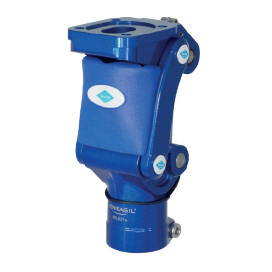
KnieAgil®-Gelenke Gebrauchsanweisung WLD31 Beschreibung Technische Angaben KA.WLD31 Gesamtlänge, total 147 mm Gewicht (inkl. Adaption) 624 g Max. Flexion 145 ° AP Verschiebung max. 5 mm Indikation Aktivitätsgrad: 1 bis 3 und für den Einsatz in Süßwasser zugelassen Das KnieAgil® WLD 31 ist ein wasserfestes, 4achsiges Gelenk mit manueller Sperre. - Page 15 KnieAgil®-Gelenke Gebrauchsanweisung WLD31 Lieferumfang Aufbau Produkt KA.WLD31 KnieAgil® WLD 31 Feder, weich KA.EA073 (beiliegend) 90.395.093.01 Gebrauchsanweisung Zubehör Produkt Das KnieAgil® Gelenk WLD 31 wird nach Notwendiges Zubehör (bitte wählen der TKALinie aufgebaut. Die Belastungs Sie eine der proximalen Adaptionen) linie des Prothesenschaftes soll an der KA.KPA-10AS Pyramidadapter Vorderkante der vorderen, oberen...
- Page 16 KnieAgil®-Gelenke Gebrauchsanweisung WLD31 Das WLD 31 verfügt über eine Sperre, Anpassen der Extensionsgeschwindigkeit die 2 Funktionen bietet: Im distalen Rohranschluss befindet sich Wird sie über den Kabelzug entriegelt, die Vorbringerfeder (einstellbar durch kann der Patient das Knie beugen. Schlitzschraube). Diese ist im Ausliefer Bei Streckung des Knies verriegelt ungszustand auf eine mittlere Exten...
- Page 17 KnieAgil®-Gelenke Gebrauchsanweisung WLD31 Hineindrehen Flexion stärker Hineindrehen Knieoberteil erhält mehr gedämpft Flexionstellung – Gelenk Herausdrehen Flexion schwächer ist leichter zu beugen, gedämpft die Standsicherheit wird jedoch reduziert Einstellen des Anschlags Herausdrehen Knieoberteil erhält mehr im Knieoberteil Extensionsstellung –...
-
Page 18: Ka.wld31S
KnieAgil®-Gelenke Gebrauchsanweisung WLD31s Beschreibung Technische Angaben KA.WLD31s Gesamtlänge, total 147 mm Gewicht (inkl. Adaption) 775 g Max. Flexion 145 ° AP Verschiebung max. 5 mm Indikation Aktivitätsgrad: 1 bis 3 und für den Einsatz in Süßwasser zugelassen Das KnieAgil® WLD 31s ist ein wasserfes tes, 4achsiges Gelenk mit manueller Sperre. - Page 19 KnieAgil®-Gelenke Gebrauchsanweisung WLD31s Lieferumfang Aufbau Produkt KA.WLD31s KnieAgil® WLD31s 90.395.093.01 Gebrauchsanweisung Zubehör Produkt Notwendiges Zubehör (bitte wählen Sie eine der proximalen Adaptionen) Das KnieAgil® Gelenk WLD 31s wird nach der KA.KPA-46S Pyramidadapter TKALinie aufgebaut. Die Belastungslinie des Gewindeanschluss, Prothesenschaftes soll an der Vorderkante KA.KPA-47S 36 mm der vorderen, oberen Achse verlaufen.
- Page 20 KnieAgil®-Gelenke Gebrauchsanweisung WLD31s Das WLD 31s verfügt über eine Sperre, Anpassen der Extensionsgeschwindigkeit die 2 Funktionen bietet: Im distalen Rohranschluss befindet Wird sie über den Kabelzug entriegelt, sich die Vorbringerfeder (einstellbar kann der Patient das Knie beugen. Bei durch Schlitzschraube). Diese ist im Streckung des Knies verriegelt sich das Ausliefer ungszustand auf eine mittlere Gelenk wieder hörbar selbst.
- Page 21 KnieAgil®-Gelenke Gebrauchsanweisung WLD31s Hineindrehen Flexion stärker gedämpft Hineindrehen Knieoberteil erhält mehr Herausdrehen Flexion schwächer Flexionstellung – Gelenk gedämpft ist leichter zu beugen, die Standsicherheit wird Einstellen des Anschlags jedoch reduziert im Knieoberteil Herausdrehen Knieoberteil erhält mehr Die Einstellung des Anschlags im Knie...
-
Page 22: Ka.sl2
KnieAgil®-Gelenke Gebrauchsanweisung SL2 Beschreibung Technische Angaben KA.SL2 Gesamtlänge, total 115 mm Gewicht (inkl. Adaption) 630 g Max. Flexion 145 ° Indikation Aktivitätsgrad: 1 3 Das KnieAgil SL 2 ist ideal geeignet für die prothetische Erstversorgung. Es bietet Höchstbelastung: 125 kg die Kombination einer manuellen Sperre Die Höchstbelastung ergibt sich mit einer Bremseinheit. - Page 23 KnieAgil®-Gelenke Gebrauchsanweisung SL2 Sicherheit Aufbau Bitte beachten Sie die Sicherheits hinweise auf S. 64. REF/Größen Produkt KA.SL2 KnieAgil® SL 2 Lieferumfang Das KnieAgil Gelenk SL2 wird nach der TKALinie aufgebaut. Die Belastungslinie Produkt des Prothesenschaftes soll mittig durch die vordere und hintere Achse verlaufen. KA.SL2 KnieAgil®...
- Page 24 KnieAgil®-Gelenke Gebrauchsanweisung SL2 Dynamische Anprobe Wir empfehlen, bei der ersten Folgende Einstellungen des Gelenkes Anwendung des Gelenkes die sind möglich. Wir empfehlen, die vorge Sperrfunktion zu nutzen! Somit schlagene Reihenfolge bei der Anprobe ist sichergestellt, dass das Knie einzuhalten. gelenk in Extension verriegelt und max.
- Page 25 KnieAgil®-Gelenke Gebrauchsanweisung SL2 Einstellen der Friktion der Bremseinheit Nehmen Sie anschließend die Feinjustie • Einstellen des belastungsabhängigen rung des Ansprechverhaltens der Bremse Aktivierens der Bremse mit Schraube „#3“ vor. (Patientengewicht) • Einstellung des Ansprechverhaltens der Bremse (weicheres/härteres An sprechverhalten) Hineindrehen ...
- Page 26 KnieAgil®-Gelenke Gebrauchsanweisung SL2 Manuelle Sperre Die manuelle Sperre ist im Auslieferungs zustand aktiviert. Dies bedeutet, dass die Sperre in Extension selbsttätig einrastet. Über den Kabelzug kann sie manuell wieder gelöst werden. Der Kabelzug ist an geeigneter Stelle am Schaft zu positionieren, hierzu ist eine Ge windescheibe im Lieferumfang des Kabel...
- Page 27 KnieAgil®-Gelenke Gebrauchsanweisung SL2 Endmontage Hineindrehen reduziert ggf. Bitte beachten Sie die aufgetretenes Spiel Sicherheits hinweise auf S.65. in der Sperreinheit Herausdrehen erleichtert das Material Einrasten der Sperre Bitte beachten Sie, stets nur minimale Bitte beachten Sie die Änderungen an der Schraubenstellung Sicherheits hinweise auf S.65.
-
Page 28: Ka.ps21
KnieAgil®-Gelenke Gebrauchsanweisung PS21 Beschreibung Technische Angaben KA.PS21 Gesamtlänge, total 226 mm Gewicht (inkl. Adaption) 892 g Max. Flexion 145 ° Indikation Aktivitätsgrad: 2+ 3 Das KnieAgil® PS21 ist ein Gelenk mit belastungsabhängiger Bremseinheit und Höchstbelastung: 125kg pneumatischer Schwungphasensteuerung. Die Höchstbelastung ergibt sich aus Optisch zeichnet es sich durch eine form... - Page 29 KnieAgil®-Gelenke Gebrauchsanweisung PS21 Sicherheit Aufbau Bitte beachten Sie die Sicherheits hinweise auf S.64. REF/Größen Produkt KA.PS21 KnieAgil® PS 21 Lieferumfang Das KnieAgil® Gelenk PS21 wird nach der TKALinie aufgebaut. Die Belastungslinie Produkt des Prothesenschaftes soll an der Vorder kante der hinteren Achse verlaufen. KA.PS21 KnieAgil®...
- Page 30 KnieAgil®-Gelenke Gebrauchsanweisung PS21 Dynamische Anprobe Folgende Einstellungen des Gelenkes sind Einstellen der Friktion der Bremseinheit möglich. Wir empfehlen, die vorgeschlagene Reihenfolge bei der Anprobe einzuhalten. Das Einstellen der Friktion der Bremsein heit zur Unterstützung der Standsicher Anpassen der heit kann stufenlos eingestellt werden. Schwungphasensteuerung Die Friktion und das Ansprechverhalten Das KnieAgil®...
- Page 31 KnieAgil®-Gelenke Gebrauchsanweisung PS21 Endmontage Notizen Bitte beachten Sie die Sicherheits hinweise auf S. 65. Material Bitte beachten Sie die Sicherheits hinweise auf S. 65. Produktpflege/ Reinigung/Wartung Bitte beachten Sie die Sicherheits hinweise auf S. 65. Lagerung/Entsorgung Bitte beachten Sie die Sicherheits hinweise auf S.
- Page 32 KnieAgil®-Gelenke Gebrauchsanweisung P41 Beschreibung Technische Angaben KA.P41 Gesamtlänge, total 204 mm Gewicht (inkl. Adaption) 846 g Max. Flexion 141° AP Verschiebung max. 5 mm Indikation Aktivitätsgrad: 2 + 3 Das KnieAgil® P 41 ist ein CNC gefertig tes pneumatisches 4AchsGelenk für hö here Belastung.
- Page 33 KnieAgil®-Gelenke Gebrauchsanweisung P41 Lieferumfang Aufbau Produkt KA.P41 KnieAgil® P 41 90.395.093.01 Gebrauchsanweisung Zubehör Produkt Notwendiges Zubehör (bitte wählen Sie eine der proximalen Adaptionen) Das KnieAgil® Gelenk P41 wird nach der KA.KPA-33A Pyramidadapter TKALinie aufgebaut. Die Belastungs linie des Prothesenschaftes soll an der KA.KPA- EingussankerSet Vorderkante der vorderen, oberen Achse...
- Page 34 KnieAgil®-Gelenke Gebrauchsanweisung P41 Dynamische Anprobe Folgende Einstellungen des Gelenkes sind Das Gelenk bietet die Möglichkeit, den möglich. Wir empfehlen, die vorgeschlagene proxi mal aufgeschraubten Adapter in ap Reihenfolge bei der Anprobe einzuhalten. Richtung um max. 5 mm zu verschieben. Damit kann Einfluss auf die Standsicher Anpassen der heit genommen werden.
- Page 35 KnieAgil®-Gelenke Gebrauchsanweisung P41 Endmontage Notizen Bitte beachten Sie die Sicherheits hinweise auf S. 65. Material Bitte beachten Sie die Sicherheits hinweise auf S. 65. Produktpflege/ Reinigung/Wartung Bitte beachten Sie die Sicherheits hinweise auf S. 65. Lagerung/Entsorgung Bitte beachten Sie die Sicherheits hinweise auf S.
-
Page 36: Ka.p44C
KnieAgil®-Gelenke Gebrauchsanweisung P44c Beschreibung Technische Angaben KA.P44c Gesamtlänge, total 166 mm Gewicht (KA.P44c) 669 g Max. Flexion 145 ° Indikation Aktivitätsgrad: 2 + 3 Das KnieAgil® P 44c ist ein pneumatisches 4Achs Kniegelenk. Sein besonders gefäl Höchstbelastung: 100 kg liges Design zeichnen es ebenso aus wie Die Höchstbelastung ergibt sich aus sein geringes Gewicht. - Page 37 KnieAgil®-Gelenke Gebrauchsanweisung P44c Sicherheit Aufbau Bitte beachten Sie die Sicherheits hinweise auf S. 64. REF/Größen Produkt KA.P44c KnieAgil® P 44c Lieferumfang Das KnieAgil® Gelenk P 44c wird nach der TKALinie aufgebaut. Die Belastungs Produkt linie des Prothesenschaftes soll durch die vordere, obere Achse verlaufen.
- Page 38 KnieAgil®-Gelenke Gebrauchsanweisung P44c Dynamische Anprobe Anpassen der Standphasensicherheit Die polyzentrische Geometrie des P 44c sorgt für eine hohe Standsicherheit des Gelenkes im gestreckten Zustand des Beines. Sie können in einem gewissen Bereich beeinflussen, ob das Gelenk auf mehr Sicherheit (höherer Widerstand beim Einleiten des Einbeugens) oder mehr Dynamik justiert werden soll.
- Page 39 KnieAgil®-Gelenke Gebrauchsanweisung P44c Endmontage Notizen Bitte beachten Sie die Sicherheits hinweise auf S.65. Material Bitte beachten Sie die Sicherheits hinweise auf S.65. Produktpflege/ Reinigung/Wartung Bitte beachten Sie die Sicherheits hinweise auf S.65. Lagerung/Entsorgung Bitte beachten Sie die Sicherheits hinweise auf S.65.
-
Page 40: Ka.psb60
KnieAgil®-Gelenke Gebrauchsanweisung PSB60 Beschreibung Technische Angaben KA.PSB60 Gesamtlänge, total 238 mm Gewicht (inkl. Adaption) 1155 g Max. Flexion 145 ° Bouncing 12° Indikation Aktivitätsgrad: 2 + 3 Das KnieAgil® PSB 60 ist ein pneumatisches Gelenk mit Bremseinheit. Die Besonderheit dieses Gelenkes ist das zusätzliche Boun Höchstbelastung: 100 kg cingElement, welches für das gleicherma... - Page 41 KnieAgil®-Gelenke Gebrauchsanweisung PSB60 Lieferumfang Aufbau Produkt KA.PSB60 KnieAgil® PSB 60 90.395.093.01 Gebrauchsanweisung Zubehör Produkt Optionales Zubehör 21.989.003.00 Schaumkosmetik Das KnieAgil® Gelenk PSB60 wird nach Feder für KA.PSB 60, der TKALinie aufgebaut. Die Belastungs KA.EA043P weich linie des Prothesenschaftes soll durch die Feder für KA.PSB Vorderkante der hinteren Achse verlaufen.
- Page 42 KnieAgil®-Gelenke Gebrauchsanweisung PSB60 Dynamische Anprobe Folgende Einstellungen des Gelenkes sind Einstellen der Friktion der Bremseinheit möglich. Wir empfehlen, die vorgeschlagene Bitte beachten: Reihenfolge bei der Anprobe einzuhalten. Verdeutlichen Sie ihrem Patienten, dass die Funktion der Stand Einstellen des phasen sichernden Bremseinheit durch Bouncing-Elementes Belastung der Bremse aktiviert wird.
- Page 43 KnieAgil®-Gelenke Gebrauchsanweisung PSB60 Endmontage Hineindrehen Aktivieren der Friktions Bitte beachten Sie die bremse bei höherer Sicherheits hinweise auf S. 65. Krafteinwirkung Herausdrehen Aktivieren der Material Friktionsbremse bereits bei geringerer Krafteinwirkung Bitte beachten Sie die Sicherheits hinweise auf S. 65. Ziehen Sie nach erfolgter Einstellung die Sicherungsschraube „#53“...
-
Page 44: Ka.pf50
KnieAgil®-Gelenke Gebrauchsanweisung PF50 Beschreibung Technische Angaben KA.PF50 Gesamtlänge, total 243 mm Gewicht (inkl. Adaption) 1155 g Max. Flexion 145 ° Bouncing 12° Indikation Aktivitätsgrad: 2 + 3 Das KnieAgil® PF 50 ist ein pneuma tisches 4Achs Gelenk mit zusätzlichem BouncingElement. Die Bouncing Höchstbelastung: 136 kg Funktion sorgt für ein sehr komfortables Die Höchstbelastung ergibt sich... - Page 45 KnieAgil®-Gelenke Gebrauchsanweisung PF50 Lieferumfang Aufbau Produkt KA.PF50 KnieAgil® PF 50 90.395.093.01 Gebrauchsanweisung Zubehör Produkt Optionales Zubehör 21.989.003.00 Schaumkosmetik Das KnieAgil® Gelenk PF50 wird nach Feder für KA.PF50, der TKALinie aufgebaut. Die Belastungs KA.EA075 weich linie des Prothesenschaftes soll durch die vor dere, obere Achse verlaufen.
- Page 46 KnieAgil®-Gelenke Gebrauchsanweisung PF50 Dynamische Anprobe Folgende Einstellungen des Gelenkes sind Einstellen des Bouncing-Elementes möglich. Wir empfehlen, die vorgeschlagene Das Kniegelenk PF50 wird mit weichen Reihenfolge bei der Anprobe einzuhalten. Dämpfungspuffern ausgeliefert. Als optiona les Zubehör können härtere Puffer bestellt Einstellen der werden, dies ist ggf.
- Page 47 KnieAgil®-Gelenke Gebrauchsanweisung PF50 Endmontage Notizen Bitte beachten Sie die Sicherheits hinweise auf S. 65. Material Bitte beachten Sie die Sicherheits hinweise auf S. 65. Produktpflege/ Reinigung/Wartung Bitte beachten Sie die Sicherheits hinweise auf S. 65. Lagerung/Entsorgung Bitte beachten Sie die Sicherheits hinweise auf S.65.
-
Page 48: Ka.r1
KnieAgil®-Gelenke Gebrauchsanweisung R1 Beschreibung Technische Angaben KA.R1 Gesamtlänge, total 175 mm Gewicht (inkl. Adaption) 1004 g Max. Flexion 147 ° Bouncing 12 ° Indikation Aktivitätsgrad: 2 + 3+ Das KnieAgil® R1 ist ein hydraulisches 4Achs Gelenk mit zusätzlichem Boun cingElement. Die Hydraulik ist in Form Höchstbelastung: 136 kg einer Rotationshydraulik integriert, die bei Die Höchstbelastung ergibt sich aus der... - Page 49 KnieAgil®-Gelenke Gebrauchsanweisung R1 Lieferumfang Aufbau Produkt KA.R1 KnieAgil® R1 90.395.093.01 Gebrauchsanweisung Zubehör Produkt Optionales Zubehör 21.989.002.00 Schaumkosmetik Beim KnieAgil® Gelenk R1 soll beim Feder weich Prothesenaufbau die Belastungslinie des KA.EA076 Prothesenschaftes im Bereich zwischen Feder hart KA.EA080 mittig durch die vordere obere Achse Dämpfer für KA.AG115 bis Vorderkante der Achsschraube des...
- Page 50 KnieAgil®-Gelenke Gebrauchsanweisung R1 Dynamische Anprobe Bitte entfernen Sie zunächst die Individuelle Einstellung Knieabdeckkappe, um alle notwendigen Hineindrehen Höhere Gehgeschwindigkeit: Einstellungen vornehmen zu können. Dämpfung erhöhen Auf den Seiten des Gelenkes befinden Herausdrehen Niedrigere Gehgeschwindig sich die Einstellschrauben für Flexion keit: Dämpfung verringern und Extension.
- Page 51 KnieAgil®-Gelenke Gebrauchsanweisung R1 Einstellung der Extensionsfeder Im Uhrzeigersinn: stärkere Vorspannung • Die unter der Abdeckung befindliche Fe der dient der Extensionsunterstützung. • Die vordere Feder (orange) verfügt über eine Überwurfmutter mit Skalierung (15), mit der die Vorspannung der Feder erhöht oder verringert werden kann. •...
- Page 52 KnieAgil®-Gelenke Gebrauchsanweisung R1 Einstellstift in Bohrung einstecken. Neue Feder einsetzen. Einstellung Dämpfungseinheit (Bouncing) • Die distal im Rohransatz positionierte Inbusschraube wirkt auf die StanceFle xion Dämpfungseinheit. Deren Vorspan nung kann eingestellt werden. • Inbusschraube im Uhrzeigersinn hinein drehen – Vorspannung der Dämpfungs einheit wird erhöht.
- Page 53 KnieAgil®-Gelenke Gebrauchsanweisung R1 Wechsel der Dämpfungseinsätze Dämpfungsanschläge vorsichtig heraushebeln. Die Inbusschraube vorsichtig bis zum Anschlag eindrehen. Neue Dämpfungsanschläge einsetzen. Drehen Sie die Inbusschraube wieder in die gewünschte Vorspannung zurück.
- Page 54 KnieAgil®-Gelenke Gebrauchsanweisung R1 Endmontage Notizen Bitte beachten Sie die Sicherheits hinweise auf S.65. Material Bitte beachten Sie die Sicherheits hinweise auf S.65. Produktpflege/ Reinigung/Wartung Bitte beachten Sie die Sicherheits hinweise auf S.65. Lagerung/Entsorgung Bitte beachten Sie die Sicherheits hinweise auf S.65.
- Page 55 KnieAgil®-Gelenke Gebrauchsanweisung R1...
-
Page 56: Ka.wkl10
KnieAgil®-Gelenke Gebrauchsanweisung Kindergelenk KA.WKL10 Beschreibung Technische Angaben KA.WKL10 Gesamtlänge, total 110 mm Gewicht (inkl. Adaption) 324 g Max. Flexion 140° Indikation Aktivitätsgrad: 1 + 2 wasserfest Das Kindergelenk KA.WKL10 ist ein mecha nisches 4Achs Gelenk mit manueller Sper Höchstbelastung: 55 kg re. -
Page 57: Sicherheit
KnieAgil®-Gelenke Gebrauchsanweisung Kindergelenk KA.WKL10 Sicherheit Aufbau Bitte beachten Sie die Das KnieAgil Gelenk WKL10 wird nach Sicherheits hinweise auf S. 64. der TKALinie aufgebaut. Die vordere, obere Achsmitte ist im Regelfall der Aufbaubezugspunkt. REF/Größen Statische Anprobe Produkt KA.WKL10 KnieAgil® KA.WKL10 Jedes Kniegelenk ist bereits mit einer Grundjustierung eingestellt. - Page 58 KnieAgil®-Gelenke Gebrauchsanweisung Kindergelenk KA.WKL10 Dauerhaftes Deaktivieren der Sperre Einstellen der Federvorspannung: Zum dauerhaften Deaktivieren die Sperre öffnen und in geöffnetem Zustand die Hineindrehen der Vorbringerfedeschraube: beiden Inbusschrauben links und rechts stärkere Schwungphasen der Sperre anziehen. unterstützung Höhere Geh geschwindigkeit Herausdrehen ...
-
Page 59: Endmontage
KnieAgil®-Gelenke Gebrauchsanweisung Kindergelenk KA.WKL10 Endmontage Einstellen der Achsfriktion Bitte beachten Sie die Sicherheits hinweise auf S.65. Die Achsfriktion kann über eine Schraube eingestellt werden, die auf die hintere Material untere Achse wirkt (siehe Abb.). Hineindrehen der Schrauben: Erhöhte Bitte beachten Sie die Friktion auf die Achse –... - Page 60 KnieAgil®-Gelenke Gebrauchsanweisung Kindergelenk KA.WK11 Beschreibung Technische Angaben KA.WK11 Gesamtlänge, total 110 mm Gewicht (inkl. Adaption) 324 g Max. Flexion 140° Indikation Aktivitätsgrad: 1 3 Das KnieAgil KA.WK11 ist ein mecha nisches 4Achs Gelenk. Die Schwung Höchstbelastung: 55 kg phasensteuerung erfolgt mechanisch durch Federvorbringer und kann zu...
- Page 61 KnieAgil®-Gelenke Gebrauchsanweisung Kindergelenk KA.WK11 Sicherheit Aufbau Bitte beachten Sie die Das KnieAgil Gelenk WK11 wird nach der Sicherheits hinweise auf S. 64. TKALinie aufgebaut. Die vordere, obere Achsmitte ist im Regelfall der Aufbau bezugspunkt. REF/Größen Statische Anprobe Produkt KA.WK11 KnieAgil® KA.WK11 Jedes Kniegelenk ist bereits mit einer Grundjustierung eingestellt.
- Page 62 KnieAgil®-Gelenke Gebrauchsanweisung Kindergelenk KA.WK11 Dynamische Anprobe Zum Einstellen der Schwungphase kann Einstellen der Achsfriktion: sowohl die Federvorspannung, als auch die Achsfriktion im Knieoberteil eingestellt Die Achsfriktion kann über eine Schraube werden. Es ist zu beachten, dass Vorbring eingestellt werden, die auf die hintere erfeder...
- Page 63 KnieAgil®-Gelenke Gebrauchsanweisung Kindergelenk KA.WK11 Endmontage Notizen Bitte beachten Sie die Sicherheits hinweise auf S.65. Material Bitte beachten Sie die Sicherheits hinweise auf S.65. Produktpflege/ Reinigung/Wartung Bitte beachten Sie die Sicherheits hinweise auf S.65. Lagerung/Entsorgung Bitte beachten Sie die Sicherheits hinweise auf S.65.
- Page 64 KnieAgil®-Gelenke Gebrauchsanweisung Sicherheit • Vor Benutzung ist eine individuelle • Der Einsatz geprüfter Einzelkompo nenten mit CEKennzeichen entbin Anpassung des Bauteils und der Prothese, in der dieses Bauteil zum det den Techniker nicht von seiner Einsatz kommt, erforderlich. Verpflichtung, die Passteilkombination •...
- Page 65 KnieAgil®-Gelenke Gebrauchsanweisung Material • Im Schadensfall gilt: Bei Kombination Titan von ModularProthesenkomponenten Aluminium unterschiedlicher Hersteller kann jeder Edelstahl Hersteller grundsätzlich nur für das Kunststoff Versagen der eigenen Passteile haftbar gemacht werden. Eine darüber hinaus Produktpflege/ gehende Haftung des Herstellers ist Reinigung/Wartung nur dann möglich, wenn seine Passteile nachweislich ursächlich für den Schaden...
-
Page 66: Haftung
KnieAgil®-Gelenke Gebrauchsanweisung Haftung Zeichenerklärung Der Hersteller empfiehlt, das Produkt nur Hersteller unter den vorgegebenen Bedingungen und zu den vorgesehenen Zwecken, Bevollmächtigter in der sowie mit den für die Prothese geprüf Europäischen Gemeinschaft ten ModularBauteilKombinationen zu verwenden und es entsprechend der Ge Chargencode brauchsanleitung zu pflegen. - Page 67 KnieAgil®-Gelenke Gebrauchsanweisung Notizen...
-
Page 68: Ka.s20
KnieAgil® Joints User Manual S20 Contents Description KA.S20 Please consider the safety notes for all of the joints! KA.S20 KA.L30 KA.LD31 KA.WLD31 KA.WLD31s The KnieAgil® S20 is a monocentric brake KA.SL2 joint with a loaddependent brake unit. KA.PS21 The brake unit is infinitely variable. The KA.P41 joint features both a distal and a proximal KA.P44c... -
Page 69: Ka.s20
KnieAgil® Joints User Manual S20 Specification Scope of Delivery Product Total length 75 mm Weight (including adapter) 533 g KA.S20 KnieAgil® S 20 90.395.093.01 User Manual Maximum flexion 140 ° Indication Accessories Product Activity level: 1 + 2 Optional Accessoires 21.989.001.00 Cosmetic Foam Cover Maximum load: 125 kg... - Page 70 KnieAgil® Joints User Manual S20 Alignment Adjusting the Brake Unit Friction The brake unit friction can be adjusted with the screws #7 and #22. Take the patient’ s weight into consideration when adjusting the friction of the brake unit. First, open the lock screw #17.
- Page 71 KnieAgil® Joints User Manual S20 Notes Then, use screw #2 to fix the plastic clamp into a position that allows fot the exten sion assist cable to be attached with a certain amount of tension. Make sure that the extension assist cable is also under tension when the joint is fully extended.
-
Page 72: Ka.l30
KnieAgil® Joints User Manual L30 Description Specification KA.L30 Total length 135 mm Weight (including adapter) 630 g Maximum flexion 145 ° Indication Activity level: 1 + 2 The KnieAgil® L 30 is a fouraxis knee joint with a manual lock. In extension, the Maximum load: 125 kg security lock audibly locks into place. - Page 73 KnieAgil® Joints User Manual L30 Safety Alignment Please follow the safety instructions on page 130. REF/Sizes Product KA.L30 KnieAgil® L 30 Scope of Delivery The alignment of the KnieAgil® L30 should be based on the TKA line. The load line of the socket should run Product along the front edge of the superior KA.L30...
- Page 74 KnieAgil® Joints User Manual L30 Static Fitting Upon delivery, every joint is set to Adjusting Axis Friction for Flexion Damping a basic setting. An Allen screw is visible in the posterior Ask the patient to stand up. Remain close, rubber coating. This screw can be used to so you can support the patient if necessary adjust the axis friction, which dampens the flexion of the joint.
- Page 75 KnieAgil® Joints User Manual L30 Final Assembly Tighten the screw Lock locks only with Please follow the safety higher load. instructions on page 131. Loosen the screw Lock locks with relatively little load. Material This setting should be individually adjusted for each patient.
-
Page 76: Ka.ld31
KnieAgil® Joints User Manual LD31 Description Specification KA.LD31 Total length 147 mm Weight (including adapter) 630 g Maximum flexion 145 ° AP offset max. 5 mm Indication Activity level: 1 + 2 The KnieAgil® LD 31 is a fouraxis joint with a manual locking mechanism. - Page 77 KnieAgil® Joints User Manual LD31 Scope of Delivery Alignment Product KA.LD31 KnieAgil® LD 31 90.395.093.01 User Manual Accessories Product The alignment of the KnieAgil® LD 31 should be based on the TKA line. The load Required Accessories line of the socket should run along the front (select one of the proximal adapters) edge of the superior anterior axis.
- Page 78 KnieAgil® Joints User Manual LD31 There is one Allen screw to the left and Tighten the screw Higher extension one to the right of the lock. With these speed screws, the lock can be permanently Loosen the screw Lower extension deactivated.
- Page 79 KnieAgil® Joints User Manual LD31 Adjusting the Stop for the Top Loosen the screw the top part of Part of the Joint the knee joint is The adjustment of the stop on the top moved into a more part of the joint serves two purposes: extended position ...
-
Page 80: Ka.wld31
KnieAgil® Joints User Manual WLD31 Description Specification KA.WLD31 Total length 147 mm Weight (including adapter) 624 g Maximum flexion 145 ° AP offset max. 5 mm Indication Activity level: 1 to 3. Approved for use in fresh water. The KnieAgil® WLD 31 is a waterproof four axis joint with a manual locking mechanism. - Page 81 KnieAgil® Joints User Manual WLD31 Scope of Delivery Alignment Product KA.WLD31 KnieAgil® WLD 31 KA.EA073 Spring, soft (included) 90.395.093.01 User Manual Accessories Product Required Accessories The alignment of the KnieAgil® WLD 31 (select one of the proximal adapters) should be based on the TKA line. The load KA.KPA-10AS Pyramid Adapter line of the socket should run along the front...
- Page 82 KnieAgil® Joints User Manual WLD31 The lock of the WLD 31 offers two functions: Adjusting the Extension Speed The extension assist spring is located in the When the joint is unlocked with the distal pylon adapter. It can be adjusted by way cable, the patient can flex his knee.
- Page 83 KnieAgil® Joints User Manual WLD31 Adjusting the Stop for the Loosen the screw the top part of the Top Part of the Joint knee joint is moved The adjustment of the stop on the top part into a more extended of the joint serves two purposes: position ...
-
Page 84: Ka.wld31S
KnieAgil® Joints User Manual WLD31s Description Specification KA.WLD31s Total length 147 mm Weight (including adapter) 775 g Maximum flexion 145 ° AP offset max. 5 mm Indication Activity level: 1 to 3. Approved for use in fresh water. The KnieAgil® WLD 31s is a waterproof fouraxis joint with a manual locking wasserfest mechanism. - Page 85 KnieAgil® Joints User Manual WLD31s Scope of Delivery Alignment Product KA.WLD31s KnieAgil® WLD31s 90.395.093.01 User Manual Accessories Product Required Accessories (please select one of the proximal adapters) The alignment of the KnieAgil® WLD 31s KA.KPA-46S Pyramid Adapter should be based on the TKA line. The load Threaded Connector line of the socket should run along the KA.KPA-47S...
- Page 86 KnieAgil® Joints User Manual WLD31s The lock of the WLD 31s offers Adjusting the Extension Speed two functions: The extension assist spring is located in the distal pylon adapter. It can be When the joint is unlocked with the adjusted by way of a slotted screw. cable, the patient can flex his knee.
- Page 87 KnieAgil® Joints User Manual WLD31s An Allen screw labeled „#1“ is visible in Tighten the screw the top part of the the posterior rubber coating. This screw knee joint is moved can be used to adjust the axis friction, into a more flexed which dampens the flexion of the joint.
-
Page 88: Ka.sl2
KnieAgil® Joints User Manual SL2 Description Technical Data KA.SL2 Total length 115 mm Weight (including adapter) 630 g Maximum flexion 145 ° Indication Activity level: 1 to 3 The KnieAgil® SL 2 is perfectly suited for building an initial prosthesis. It combines a Maximum load: 125 kg manual lock with a brake unit. - Page 89 KnieAgil® Joints User Manual SL2 Safety Aufbau Please follow the safety instructions on page 130. REF/Sizes Product KA.SL2 KnieAgil® SL 2 Scope of Delivery The alignment of the KnieAgil® S20 should be based on the TKA line. The load line of Product the socket should run through the center of the anterior and the posterior axis.
- Page 90 KnieAgil® Joints User Manual SL2 Dynamic Fitting We recommend setting the joint The joint settings listed below can be ad to lock mode for the first use. justed if desired. We recommend following This way, you can be sure that the suggested order of adjustments.
- Page 91 KnieAgil® Joints User Manual SL2 Adjusting the Brake Unit Friction The brake unit of the joint is adjusted in two steps: • Adjusting the loaddependent activation of the brake (user’s weight) • Adjusting the brake response (softer/harder response) Tighten the screw More direct brake response (lower force application required) Loosen the screw ...
- Page 92 KnieAgil® Joints User Manual SL2 Manual Lock The joint is delivered with the manual lock activated. This means that the lock will auto matically lock in extension. It can be manually released by pulling the release cable. Position the release cable in a suitable spot on the socket.
- Page 93 KnieAgil® Joints User Manual SL2 Final Assembly Tighten the screw Lock unit is tightened Please follow the safety to reduce possible instructions on page 131. play within the unit Loosen the screw Lock will catch Material more easily Always only make minor adjustments to Please follow the safety the screws.
-
Page 94: Ka.ps21
KnieAgil® Joints User Manual PS21 Description Specification KA.PS21 Total length Weight (including adapter) 892 g Maximum flexion 145 ° Indication Activity level: 2+ 3 The KnieAgil® PS 21 is a joint with a loaddependent brake unit and pneumatic swing phase control. The joint features a Maximum load: 125kg visually appealing, slim design, a smooth... - Page 95 KnieAgil® Joints User Manual PS21 Safety Alignment Please follow the safety instructions on page 131. REF/Sizes Product KA.PS21 KnieAgil® PS 21 Scope of Delivery The alignment of the KnieAgil® PS21 should be based on the TKA line. The Product load line of the socket should run along the front edge of the posterior axis.
- Page 96 KnieAgil® Joints User Manual PS21 Dynamic Fitting The following joint settings can be adjusted Adjusting the Brake Unit Friction if desired. We recommend following the The brake unit friction can be adjusted suggested order of adjustments. continuously, to improve standing stability. Adjusting Swing Phase Control The friction and the response behavior of On the KnieAgil®...
- Page 97 KnieAgil® Joints User Manual PS21 Final Assembly Notes Please follow the safety instructions on page 131. Material Please follow the safety instructions on page 131. Product Care/Cleaning/ Maintenance Please follow the safety instructions on page 131. Storage/Disposal Please follow the safety instructions on page 131.
-
Page 98: Ka.p41
KnieAgil® Joints User Manual P41 Description Specification KA.P41 Total length 204 mm Weight (including adapter) 846 g Maximum flexion 141° AP offset max. 5 mm Indication Activity level: 2 + 3 The KnieAgil® P 41 is a CNCcrafted pneumatic fouraxis joint, suitable for higher loads. - Page 99 KnieAgil® Joints User Manual P41 Scope of Delivery Alignment Product KA.P41 KnieAgil® P 41 90.395.093.01 User Manual Accessories Product Required Accessories KA.KPA-33A Pyramid Adapter The alignment of the KnieAgil® P41 should be based on the TKA line. The load KA.KPA- Lamination Anchor line of the socket should run along the SET-03-34...
- Page 100 KnieAgil® Joints User Manual P41 Dynamic Fitting The following joint settings are can be The joint allows for the AP position of adjusted if desired. We recommend follow the adapter to be moved by a maximum ing the suggested order of adjustments. of 5mm.
- Page 101 KnieAgil® Joints User Manual P41 Final Assembly Notes Please follow the safety instructions on page 131. Material Please follow the safety instructions on page 131. Product Care/Cleaning/ Maintenance Please follow the safety instructions on page 131. Storage/Disposal Please follow the safety instructions on page 131.
-
Page 102: Ka.p44C
KnieAgil® Joints User Manual P44c Description Specification KA.P44c Total length 166 mm Weight 669 g Maximum flexion 145 ° Indication Activity level: 2 + 3 The KnieAgil® P 44c is a pneumatic four axis knee joint. It combines exceptionally Maximum load: 100 kg appealing design with very light weight. - Page 103 KnieAgil® Joints User Manual P44c Safety Alignment Please follow the safety instructions on page 130. REF/Sizes Product KA.P44c KnieAgil® P 40 Scope of Delivery The alignment of the KnieAgil® P 44c should be based on the TKA line. The load line of the socket should run through the Product superior anterior axis.
- Page 104 KnieAgil® Joints User Manual P44c Dynamic Fitting Adjusting Stance Phase Stability The polycentric geometry of the P44c makes for high stance phase stability of the joint when the leg is extended. Within limits, you can influence whether the joint should be adjusted so it is more secure (higher resistance when flexion is initiated) or more dynamic.
- Page 105 KnieAgil® Joints User Manual P44c Final Assembly Notes Please follow the safety instructions on page 131. Material Please follow the safety instructions on page 131. Product Care/Cleaning/ Maintenance Please follow the safety instructions on page 131. Storage/Disposal Please follow the safety instructions on page 131.
-
Page 106: Ka.psb60
KnieAgil® Joints User Manual PSB60 Description Specification KA.PSB60 Total length 238 mm Weight (including adapter) 1155 g Maximum flexion 145 ° Stance flexion 12° Indication Activity level: 2 + 3 The KnieAgil® PSB 60 is a pneumatic joint with an integrated brake unit. This knee joint‘s most special property is its Maximum load: 100 kg additional stance flexion feature, which... - Page 107 KnieAgil® Joints User Manual PSB60 Scope of Delivery Alignment Product KA.PF50 KnieAgil® PF 50 90.395.093.01 User Manual Accessories Product Optional Accessoires 21.989.003.00 Cosmetic Foam Cover The alignment of the KnieAgil® PSB60 should be based on the TKA line. The load Spring for KA.EA043P KA.PSB 60, soft...
- Page 108 KnieAgil® Joints User Manual PSB60 Dynamic Fitting The following joint settings can be adjusted Adjusting the Brake Unit Friction Please Note: if desired. We recommend following the Make sure your patient suggested order of adjustments. understands that the brake unit, which increases the safety during stance phase, Adjusting the Stance Flexion Unit gets activated when weight is put on the...
- Page 109 KnieAgil® Joints User Manual PSB60 Final Assembly Tighten the screw Hihger load is Please follow the safety needed to activate instructions on page 131. the friction brake Loosen the screw Lower load is Material needed to activate the friction brake Please follow the safety Once the adjustment is finished, tighten instructions on page 131.
-
Page 110: Ka.pf50
KnieAgil® Joints User Manual PF50 Description Specification KA.PF50 Total length 243 mm Weight (including adapter) 1155 g Maximum flexion 145 ° Stance flexion 12° Indication Activity level: 2 + 3 The KnieAgil® PF 50 is a pneumatic 4axis kneejoint with additional stance flexion. The stance flexion feature ensures a very Maximum load: 136 kg comfortable feel and reduces the effect of... - Page 111 KnieAgil® Joints User Manual PF50 Scope of Delivery Alignment Product KA.PF50 KnieAgil® PF 50 90.395.093.01 User Manual Accessories Product Optional Accessoires 21.989.003.00 Cosmetic Foam Cover The alignment of the KnieAgil® PF50 Spring for should be based on the TKA line. The load KA.EA075 KA.PF50, soft line of the socket should run through the...
- Page 112 KnieAgil® Joints User Manual PF50 Dynamic Fitting The following joint settings can be adjusted Adjusting the Stance Flexion Unit if desired. We recommend following the The knee joint PF50 is delivered with soft suggested order of adjustments. rubber dampers installed. Harder dampers are available as optional accessories, and Adjusting the Pneumatic Damping may be recommendable for users with a...
- Page 113 KnieAgil® Joints User Manual PF50 Final Assembly Notes Please follow the safety instructions on page 131. Material Please follow the safety instructions on page 131. Product Care/Cleaning/ Maintenance Please follow the safety instructions on page 131. Storage/Disposal Please follow the safety instructions on page 131.
-
Page 114: Ka.r1
KnieAgil® Joints User Manual R1 Description Specification KA.R1 Total length 175 mm Weight (including adapter) 1004 g Maximum flexion 147 ° Stance flexion 12 ° Indication Activity level: 2 + 3+ The KnieAgil® R1 is a hydraulic 4axis joint with an additional stanceflexion function. - Page 115 KnieAgil® Joints User Manual R1 Scope of Delivery Alignment Product KA.R1 KnieAgil® R1 90.395.093.01 User Manual Accessories Product Optional Accessories 21.989.002.00 Cosmetic Foam Cover Spring, soft KA.EA076 When the prosthesis is assembled, the Spring, hard KA.EA080 load line of the socket should run through Bumper for Stance KA.AG115 the area located between the center of...
- Page 116 KnieAgil® Joints User Manual R1 Dynamic Fitting First, remove the knee cover, so you Individual Adjustment can make all necessary adjustments. Tighten the screw Higher walking speed: The setting screws for adjusting increase damping flexion and extension are located Loosen the screw ...
- Page 117 KnieAgil® Joints User Manual R1 Turn the screw anticlockwise towards spring has been set to the lowest <> to decrease extension damping (stop initial tension possible. Please note: damping). Extension damp ing has to be decreased if the prosthesis‘ swing behaviour does not suffice to put the joint into a secure extended position.
- Page 118 KnieAgil® Joints User Manual R1 Insert adjustment key into hole. Insert new spring. Adjusting the Damping Unit (Stance Flexion) • The Allen screw that is located distally on the inside of the pylon receiver influences the stance flexion damping unit. The initial tension of this damping unit can be adjusted.
- Page 119 KnieAgil® Joints User Manual R1 Replacing the Bumpers: Insert the new bumpers. Carefully tighten the Allen screw as far as it will go. Loosen the Allen screw again until the desired initial tension is reached. Carefully pry the bumpers out.
- Page 120 KnieAgil® Joints User Manual R1 Final Assembly Notes Please follow the safety instructions on page 131. Material Please follow the safety instructions on page 131. Product Care/Cleaning/ Maintenance Please follow the safety instructions on page 131. Storage/Disposal Please follow the safety instructions on page 131.
- Page 121 KnieAgil® Joints User Manual R1 Notes...
-
Page 122: Ka.wkl10
KnieAgil® Joints User Manual Pediatric Joint KA.WKL10 Description Specification KA.WKL10 Total length 110 mm Weight (including adapter) 324 g Maximum flexion 140° Indication Activity level: 1 + 2 wasserfest The Pediatric Joint KA.WKL10 is a mechanical 4axis joint, equipped with a manual lock. Maximum load: 55 kg The lock can be released with the pull of a cable, but can also be completely deactivated... - Page 123 KnieAgil® Joints User Manual Pediatric Joint KA.WKL10 Safety Alignment The alignment of the KnieAgil® WKL10 Please follow the safety should be based on the TKA line. The front, instructions on page 130. top center of the axis usually serves as the reference point for the alignment.
- Page 124 KnieAgil® Joints User Manual Pediatric Joint KA.WKL10 Torque 1Nm Torque 15 Nm Adjust Initial Spring Tension Here To adjust the swing phase setting, both Adjusting Axis Friction the initial tension of the spring as well as the axis friction in the top part of the knee joint can be adjusted.
- Page 125 KnieAgil® Joints User Manual Pediatric Joint KA.WKL10 Final Assembly Notes Please follow the safety instructions on page 131. Material Please follow the safety instructions on page 131. Product Care/Cleaning/ Maintenance Please follow the safety instructions on page 131. Storage/Disposal Please follow the safety instructions on page 131.
-
Page 126: Ka.wk11
KnieAgil® Joints User Manual Pediatric Joint KA.WK11 Description Specification KA.WK11 Total length 110 mm Weight (including adapter) 324 g Maximum flexion 140° Indication Activity level: 1 3 wasserfest The KnieAgil® KA.WK11 is a mechanical 4axis joint. Swing phase control is per Maximum load: 55 kg formed mechanically by extension assist, and can be adjusted by changing the axis... -
Page 127: Safety
KnieAgil® Joints User Manual Pediatric Joint KA.WK11 Safety Alignment Please follow the safety The alignment of the KnieAgil® WK11 instructions on page 130. should be based on the TKA line. The front, top center of the axis usually serves as the reference point for the alignment. REF/Sizes Static Fitting Product... - Page 128 KnieAgil® Joints User Manual Pediatric Joint KA.WK11 Adjusting Initial Spring Tension Adjusting Axis Friction Tighten the spring preload screw: Axis friction can be adjusted with a More swing phase support screw which affects the lower posterior higher walking speed axis (see figure below).
-
Page 129: Final Assembly
KnieAgil® Joints User Manual Pediatric Joint KA.WK11 Final Assembly Notes Please follow the safety instructions on page 131. Material Please follow the safety instructions on page 131. Product Care/Cleaning/ Maintenance Please follow the safety instructions on page 131. Storage/Disposal Please follow the safety instructions on page 131. - Page 130 (e.g. due to a fall), they must be or can be found in the according chart checked for potential damage by an at www.teufel international.com in the orthopedic technician before further use. downloads section of the website. • If the locking torque has been lasered...
- Page 131 KnieAgil® Joints User Manual Final Assembly adapters may not have any appli cable Do not use talcum powder or any other locking torque at all, since they feature no powder. Powders bind fat and thus will screw threads (e.g. 4holeadapter cause the joint to run dry.
-
Page 132: Liability
KnieAgil® Joints User Manual Storage/Disposal Warranty Store the product in its original packaging The warranty period for KnieAgil® Joints in a dry place. Protect from dust, dirt is 24 months. and moisture. This product does not contain any environmentally hazardous Legend to Symbols substances. - Page 133 KnieAgil® Joints User Manual Notes...
- Page 134 Notizen/Notes...
- Page 135 Notizen/Notes...
- Page 136 Wilhelm Julius Teufel GmbH Robert-Bosch-Straße 15 73117 Wangen Deutschland/Germany Phone: +49 (0)7161 15684-0 Fax: +49 (0)7161 15684-333 www.teufel-international.com...
Need help?
Do you have a question about the KnieAgil Series and is the answer not in the manual?
Questions and answers