Samson 3730-3 Safety Manual
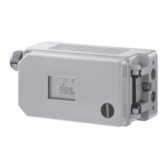
Electropneumatic positioner with hart communication 3730 series
Hide thumbs
Also See for 3730-3:
- Mounting and operating instructions (184 pages) ,
- Operating instructions manual (132 pages) ,
- Manual (2 pages)

Related Manuals for Samson 3730-3


Summary of Contents for Samson 3730-3
- Page 1 Series 3730 Type 3730-3 Electropneumatic Positioner with HART communication ® Safety Manual SH 8384-3 EN Edition December 2016...
- Page 2 The mounting and operating instructions for all supplied devices are included in the delivery. The latest versions of the documents are available on our website at www.samson.de > Product documentation. You can enter the document number or type number in the [Find:] field to look for a document.
- Page 3 Purpose of this manual The Safety Manual SH 8384-3 contains information relevant for the use of the Type 3730-3 Positioner in safety-instrumented systems according to IEC 61508 and IEC 61511. The safety manual is intended for planners, constructors, and operators of safety-instrumented systems. NOTICE Risk of malfunction due to incorrect mounting, connection or start-up of the device.
-
Page 4: Table Of Contents
Contents Scope ......................5 Technical data (excerpt from EB 8384-3) ............6 Safety-related functions .................8 Mounting, connection, and start-up ..............10 Required conditions ..................11 Proof testing ....................13 Repairs .......................15 SH 8384-3 EN... -
Page 5: Scope
Versions and ordering data Apart from the low-temperature version with metal cable gland, all versions of the Type 3730-3 Positioner are suitable for use in safety-instrumented systems. However, the op- tional equipment affects the safety-related behavior of the positioner. These options are the inductive limit contact SJ2-SN and the solenoid valve. -
Page 6: Technical Data (Excerpt From Eb 8384-3)
− Attachment to rotary actuators according to VDI/VDE 3845, fixing levels 1 and 2 2 Technical data (excerpt from EB 8384-3) Type 3730-3 Positioner: also observe the technical data in the test certificates for explosion-protected versions Signal range 4 to 20 mA · Two-wire device, reverse polarity protection · Minimum span 4 mA... - Page 7 Technical data (excerpt from EB 8384-3) Type 3730-3 Positioner: also observe the technical data in the test certificates for explosion-protected versions Sensitivity ≤0.1 % Transit time Venting or filling with air adjustable separately up to 240 s by software. To fill actuator At Δp = 6 bar: 8.5 m ³/h ·...
-
Page 8: Safety-Related Functions
Safety-related functions 3 Safety-related functions 1. Emergency venting over the i/p converter (Fig. 1 path In automatic operation, the PD controller (3) compares the actual value to the DC control signal from 4 to 20 mA coming from the microcontroller. In case of a system deviation, the activation of the i/p converter is changed so that the actuator (1) is either vented or filled with air. - Page 9 Safety-related functions Serial Serial Interface Interface 24 V DC Control valve 13* Analog position transmitter Travel sensor Software limit contact, alarm 1/2 PD controller Fault alarm output, alarm 3 A/D converter Display Microcontroller 17* Actuation of solenoid valve i/p converter 18* Electrical insulation Air capacity booster D/A converter...
-
Page 10: Mounting, Connection, And Start-Up
Mounting, connection, and start-up 4 Mounting, connection, and start-up Refer to Mounting and Operating Instructions EB 8384-3 on how to mount, perform the electric and pneumatic connections as well as start up the positioner. Only use the specified original mounting parts and accessories. +41 -42 Analog input x Not Ex: Binary input of a PLC acc. -
Page 11: Required Conditions
Required conditions 5 Required conditions WARNING Risk of malfunction due to incorrect selection or wrong installation and operating conditions. Only use control valves in safety-instrumented systems after the necessary conditions in the plant have been fulfilled. The same applies to the mounted positioner. Selection Î... - Page 12 We recommend installing a supply pressure regulator/filter upstream of the positioner. For example, the SAMSON Type 4708 Supply Pressure Regulator with 5 µm filter car- tridge can be used. Î The supply air line has a minimum inside diameter of 4 mm.
-
Page 13: Proof Testing
Regularly check the safety function according to the test plan drawn up by the operator. Note Record any faults in the positioner and inform SAMSON of them in writing. − Emergency venting by applying a 0 mA signal to terminals 11/12 (control signal): 1. - Page 14 Proof testing 6. Check whether the actuator is fully vented within the demanded time. Connect a pressure gauge to check that the actuator has completely vented. − Emergency venting by applying a 0 V signal to terminals 81/82 (solenoid valve): 1. Apply supply air within the permissible range (max. 7 bar) to the positioner which al- lows the valve to move to the maximum travel/angle of rotation.
-
Page 15: Repairs
Repairs Visual inspection to avoid systematic failure To avoid systematic failure, inspect the positioner regularly. The frequency and the scope of the inspection lie within the operator's responsibility. Take application-specific influences into account, such as: − Dirt blocking the pneumatic connections −... - Page 16 SH 8384-3 EN...
- Page 17 1 FIT = 1 failure per 10 hours Manufacturer's Declaration Changed on: 2014-06-23 2014-07-30 2014-08-21 V/HE-1142-3 DE-EN Changed by: V31/Bhk/V74/Tny V31/Bhk/V74/Tny V31/Bhk/V74/Tny SAMSON AKTIENGESELLSCHAFT · Weismüllerstraße 3 · 60314 Frankfurt am Main, Germany · Phone: +49 69 4009-0 · Fax: +49 69 4009-1507 · samson@samson.de...
- Page 18 Gebrauch verantwortlich. Manufacturer's Declaration Changed on: 2014-06-23 2014-07-30 2014-08-21 V/HE-1142-3 DE-EN Changed by: V31/Bhk/V74/Tny V31/Bhk/V74/Tny V31/Bhk/V74/Tny SAMSON AKTIENGESELLSCHAFT · Weismüllerstraße 3 · 60314 Frankfurt am Main, Germany · Phone: +49 69 4009-0 · Fax: +49 69 4009-1507 · samson@samson.de...
- Page 19 Instrumentation and Controls SAMSON GROUP Manufacturer's Declaration Changed on: 2014-06-23 2014-07-30 2014-08-21 V/HE-1142-3 DE-EN Changed by: V31/Bhk/V74/Tny V31/Bhk/V74/Tny V31/Bhk/V74/Tny SAMSON AKTIENGESELLSCHAFT · Weismüllerstraße 3 · 60314 Frankfurt am Main, Germany · Phone: +49 69 4009-0 · Fax: +49 69 4009-1507 · samson@samson.de...
- Page 20 SAMSON AG · MESS- UND REGELTECHNIK Weismüllerstraße 3 · 60314 Frankfurt am Main, Germany Phone: +49 69 4009-0 · Fax: +49 69 4009-1507 SH 8384-3 EN samson@samson.de · www.samson.de...
Need help?
Do you have a question about the 3730-3 and is the answer not in the manual?
Questions and answers