
Related Manuals for Supmeter BST106-M10


![Controller Supmeter BST106-B60[A] Operation Manual](https://static-data2.manualslib.com/product-images/b2c/1549968/60x60/supmeter-bst106-b60-a-controller.jpg)


Summary of Contents for Supmeter BST106-M10
- Page 1 BST106-M10[FB] Weighing Controller For: Ration Batching Scale with 4-material&2-speed Feeding [Single-scale Mode & Four-scale Mode] Operation Manual V5.0 Changsha Supmeter Technological Co.,Ltd.
- Page 2 Preface Thank you very much for your purchase! This manual covers safety precaution, technical specification, operation interface, installation& connection, function&operation and so on. In order to make the product running at its best, please read this manual in advance, and reserve it for the future reading. The technology update, function enhancement and quality improvement may lead to some differences between this manual and the physical product, please understand.
-
Page 3: Table Of Contents
Contents 1. SAFETY PRECAUTION .........................4 2. TECHNICAL SPECIFICATION ....................5 3. OPERATION INTERFACE ......................6 3.1 O ....................6 PERATION NTERFACE OF OGIN 3.2 M APP1 S ............7 PERATION NTERFACE FOR INGLE SCALE 3.3 M APP2 F .............. 8 PERATION NTERFACE FOR SCALE 3.4 B .......................... - Page 4 4.5.1 System Diagram A for APP2 Four-Sacle Mode without Mixing Bin ........23 4.5.2 System Diagram B for APP2 Four-Sacle Mode with Mixing Bin ..........24 4.5.3 DI/DO Connection for APP2 Four-Sacle Mode ................ 25 5. OPERATION PROCEDURE ......................26 6. FUNCTION&OPERATION ......................27 6.1 M ........................
-
Page 5: Safety Precaution
1. Safety Precaution Lithium Battery Installation A Lithium battery should be equipped in the product. If it is not allowed to be transported together with the product because of embargo, please make a purchase according to the model offered by us and install it by yourself. ... -
Page 6: Technical Specification
2. Technical Specification Executing Standard CMC GB/T 7724-2008《Electronic Weighing Meter》PRC National Standard. OMIL R76: 2006《Non-automatic Weighing Instruments》International Recommendation. Accuracy Grade: III. Verification Accuracy: 0.02%. Static Weighing Accuracy: 0.2%~0.5%. Batching Accuracy: 0.2%~0.5%. Structure&Configuration ... -
Page 7: Operation Interface
COM1[RS232]&COM2[RS485] for connecting Host IPC/PLC and LED Remote Display. COM[RS232] for connecting RS232 Serial Printer with Baud Rate ‘9600bps’, Parity Check ‘None’, 8 Data Bits and 1 Stop Bit USB1 for connecting USB mouse, downloading HMI software from U-disk and copying data to U-disk. -
Page 8: Main Operation Interface For App1 Single-Scale Mode
3.2 Main Operation Interface for APP1 Single-scale Mode Parameter [906] ‘Main Display Style’= ‘0: ZQH’: Parameter [906] ‘Main Display Style’= ‘1: GUI1’:... -
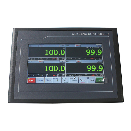
Page 9: Main Operation Interface For App2 Four-Scale Mode
3.3 Main Operation Interface for APP2 Four-scale Mode Parameter [906] ‘Main Display Style’= ‘0: ZQH’: Parameter [906] ‘Main Display Style’= ‘1: GUI1’:... -
Page 10: Button Operation
3.4 Button Operation Name Operation State Indicator Authorization Green: Auto state. 【Auto】 Auto / Manual [Emergency Stop] switch. Grey: Manual state. Green: Running state. 【Start】 Start. Grey: Stop state. 【Re-run】 Clear Alarm & Recover Running. Last Batch [Normal Stop]. 【Last】 Flashing Red. -
Page 11: Data Display & Quick Setting
3.5 Data Display & Quick Setting Name Description Authorization Biggest Digits Real-time Weight / Material Mn’s Feeding Weight [Weight Unit]. [GROSS] Gross Weight. [HI] Gross Weight Upper Limit Alarm. [OL] Overload Alarm. [CYCLES] Batch Count. [▲]/HI Positive Deviation Alarm. [▼]/LO Negative Deviation Alarm. -
Page 12: Alarm Sign
3.6 Alarm Sign 3.6.1 Alarm Message Message Alarm Cause Solution Gross Weight Upper Refer to parameter [204]-[207] ‘Gross Weight Gross Weight ≥ Upper Limit. Limit Upper Limit’. Refer to parameter [200] ‘Allowed Positive Positive Deviation Alarm. Deviation’ [201] ‘Allowed Negative Deviation Alarm Negative Deviation Alarm. -
Page 13: Error Message
3.6.3 Error Message Message Alarm Cause Solution RAM Fault The chip RAM is damaged. Replace the chip RAM. EEPROM Fault The chip EEPROM is damaged. Replace the chip EEPROM. Parameter Error The chip EEPROM is damaged. Replace the chip EEPROM. Weighing Signal Weighing signal reversed or not Connect the loadcell correctly. -
Page 14: Installation&Connection
4. Installation&Connection 4.1 Installation 4.1.1 Outline Size 7” Outline Size Panel Cut-out Size Outline Size Front Panel Size Box Body Size Panel Cut-out Size Product W×H×D[mm] W×H[mm] W×H [mm] W1×H1[mm] 7” 226.5×163×36 226.5×163 213×150 215×152 10.2” 274×193×40 274×193 259×178 261×180 4.1.2 Installation Angle The installation angle should be in the range of 0~30°. -
Page 15: Installation Mode
4.1.3 Installation Mode Before installation the front end of the screw should be flat with the edge of the hook. -
Page 16: Terminal
4.2 Terminal 4.2.1 Terminal Diagram LOADCELL COM2 COM1 1 2 3 4 5 6 7 8 9 10 11 12 2+ G 3+ 4+ 1 2 3 4 5 6 7 2 3 4 5 6 7 8 9 10 11 12 2 3 4 5 6 7 8 9 10 11 12 13 4.2.2 Power Supply Terminal Description... -
Page 17: Loadcell Terminal
4.2.3 Loadcell Terminal Description LOADCELL Loadcell Port Weigher #1 Weighing Signal [mV] Input -. Weigher #1 Weighing Signal [mV] Input +. Excitation Voltage -. Excitation Voltage + [DC5V]. Weigher #3 Weighing Signal [mV] Input -. Weigher #3 Weighing Signal [mV] Input +. Shield Ground. -
Page 18: Digital Communication Terminal
4.2.4 Digital Communication Terminal Description Special for manufacturer. COM1 RS232 Digital Communication Port [Definable] Transmit Data [TXD]. Receive Data [RXD]. COM1 Signal Ground [GND]. COM2 Shield Ground [GND]. COM2 RS485 Digital Communication Port [Definable] Data -. Data +. RS232 Serial Printer Port [DB9] Receive Data. -
Page 19: Analog&Switch Signal Terminal
4.2.5 Analog&Switch Signal Terminal Name Description 0~10V Analog Output Port [Definable] AO1+ Weigher #1 AO1 Output +. AO2+ Weigher #2 AO2 Output +. AO Output -. AO3+ Weigher #3 AO3 Output +. AO4+ Weigher #4 AO4 Output +. Switch Signal Input Port [Valid with high-level input voltage 24V] Switch Signal Input 1. -
Page 20: Di/Do Efactory Ssignment
4.3 DI/DO Ex-factory Assignment DI [Valid with high-level input voltage 24V] Signal Name Description Auto/Manual. AUTO ON: Auto state. OFF: Manual state / Emergency Stop. Start. ‘Auto/Stop’ state: Start. In ‘Auto/Running’ process: Clear Alarm [Deviation Alarm START Acknowledge] ‘Auto/Pause’ state: Clear Alarm & Recover Running. OFF→ON→OFF. - Page 21 DO [Transistor, Valid with high-level output voltage 24V] Signal Name Description DC24V Input -. M1_SP1 Material M1 High-speed Feed. M1_SP3 Material M1 Low-speed Feed. M2_SP1 Material M2 High-speed Feed. M2_SP3 Material M2 Low-speed Feed. M3_SP1 Material M3 High-speed Feed. M3_SP3 Material M3 Low-speed Feed.
-
Page 22: Typical Application: App1 Single-Sacle Mode
4.4 Typical Application: APP1 Single-sacle Mode 4.4.1 System Diagram for APP1 Single-sacle Mode Feeding Hopper M1-M4 。 。 。 SP1 High-speed Feeding Gate / SP3 Low-speed Feeding Gate Loadcell Weighing Hopper / Mixing Bin Mixer Summing Box Dumping Gate Mixing Conveyor Mixing Conveyor Ready Control Box Weighing Controller... -
Page 23: Di/Do Connection For App1 Single-Sacle Mode
4.4.2 DI/DO Connection for APP1 Single-Sacle Mode Selector Switch AUTO Auto/Manual Push Button START Push Button LAST Last Batch [Normal Stop] DUMP_I Push Button Manual Dumping BELT_START Push Button Start Mixing Conveyor BELT_STOP Push Button Stop Mixing Conveyor BELT_RDY Mixing Conveyor Ready DO [Transistor] -... -
Page 24: Typical Application: App2 Four-Sacle Mode
4.5 Typical Application: APP2 Four-Sacle Mode 4.5.1 System Diagram A for APP2 Four-Sacle Mode without Mixing Bin Feeding Hopper M1-M4 SP1 High-speed Feeding Gate / SP3 Low-speed Feeding Gate Weighing Hopper #1-#4 Loadcell Dumping Gate Mixing Conveyor Control Box Mixing Conveyor Ready Weighing Controller Parameter [300] ‘Application Mode’= ‘1: APP2 Four-scale Mode’. -
Page 25: System Diagram B For App2 Four-Sacle Mode With Mixing Bin
4.5.2 System Diagram B for APP2 Four-Sacle Mode with Mixing Bin Feeding Hopper M1-M4 SP1 High-speed Feeding Gate / SP3 Low-speed Feeding Gate Weighing Hopper #1-#4 Loadcell Dumping Gate Mixing Bin Mixer Dumping Gate Mixing Conveyor Control Box Mixing Conveyor Ready Weighing Controller Parameter [300] ‘Application Mode’= ‘1: APP2 Four-scale Mode’. -
Page 26: Di/Do Connection For App2 Four-Sacle Mode
4.5.3 DI/DO Connection for APP2 Four-Sacle Mode Selector Switch AUTO Auto/Manual Push Button START Push Button LAST Last Batch [Normal Stop] DUMP_I Push Button Manual Dumping BELT_START Push Button Start Mixing Conveyor BELT_STOP Push Button Stop Mixing Conveyor BELT_RDY Mixing Conveyor Ready DO [Transistor] -... -
Page 27: Operation Procedure
5. Operation Procedure Connection & Power on Scale Setting Zero Calibration Load Calibration [Loss Calibration] Auto Zero Tracking Range & Zero Fine Adjusting Range Setting Working Mode Setting Timer Setting Recipe Setting Other Settings Working Process Control... -
Page 28: Function&Operation
6. Function&Operation 6.1 Main Menu Interface... -
Page 29: Main Menu Function
6.2 Main Menu Function Main Menu Second Menu Description Authorization Scale Scale parameters setting. Calibration Calibration parameters setting. Setpoint Setpoint parameters setting. F1 Settings Mode Working mode parameters setting. Timer Timer parameters setting. Comm. Communication parameters setting. Engineer Display Display and operation interface parameters setting. Administrator Zero Calibration without loading on the weigher to correct Zero Value. -
Page 30: F1 Settings
6.3 F1 Settings 6.3.1 Weighing Parameters Sign Range Default Description Weight Unit Weight Unit 0: UserSet; 1: g; 2: kg; 3: t 40101 4: lb[pound]; 5: oz[ounce] Decimal Point Decimal Point Position 40103 Position 0: 0; 1: 0.0; 2: 0.00; 3: 0.000 #1 Scale Capacity Max. - Page 31 Sign Range Default Description Stablity Judging Range [d: Division] Stablity Judging Weight Variance per [109] ‘Stablity Judging 0~99 40125 Range Time’ being within [108] ‘Stablity Judging Range’ means ‘Weight is stable’. Stablity Judging 0.1~9.9 Stablity Judging Time [s] 40127 Time SP1 Anti-vibration Filter1 Anti-vibration 0~19...
-
Page 32: Calibration Parameters
6.3.2 Calibration Parameters Sign Range Default Description Auto Zero Tracking Rate Set value = 0: No ‘Auto Zero Tracking’. Set value > 0: Only when ‘Weight is stable’ and Auto Zero ‘Zero Variation Rate < Auto Zero Tracking 0.0~25.0 40151 Tracking Rate Rate’, it’s allowed to enter Auto Zero Tracking process. -
Page 33: Setpoint Parameters
6.3.3 Setpoint Parameters Sign Range Default Description Allowed Positive Deviation Positive Deviation = Final Feeding Weight – Allowed Positive 0.1~100.0 Target Value. 1.0% 40225 Deviation If ‘Positive Deviation > Target Value × Allowed Value’, the DO switch ‘Positive Deviation Alarm’ will turn on automatically. Allowed Negative Deviation Negative Deviation = Target Value –... -
Page 34: Working Mode Parameters
6.3.4 Working Mode Parameters Sign Range Default Description Application Mode Application 0: APP1 Single-scale Mode 40301 Mode 1: APP2 Four-scale Mode Authorization: Administrator. Target Batch Control Target Batch 0: OFF 40303 Control 1: ON [With Target Batch finished, batching process will stop automatically] Auto Zero Cycle Interval value=0: doing... - Page 35 Sign Range Default Description Auto SP3 Re-feed for Fall Point 0: OFF 1: ON [If the auto-feeding process stops abnormally because of heavy impact on the weighing hopper, and ‘Feeding Weight < (Target SP3 Re-feed for Value - SP3 Fall)’, the DO switch ‘SP3 40317 Fall Point Low-speed...
- Page 36 Sign Range Default Description Fall Auto Interval of Fall Value Auto Correction N Correction 1~99 After Deviation Alarm Count reached to N, Fall 40325 Interval Value will be corrected automatically. Fall Value Auto Correction Range Fall Auto If the absolute value of deviation exceeds this 40327 Correction Range ~60000...
-
Page 37: Timer Parameters
6.3.5 Timer Parameters Sign Range Default Description T1 Delay to Auto ZERO [s] Delay Time Before Auto Zero Fine Adjustment. If Auto Zero Fine Adjustment (set via parameter [302]) is not necessary before feeding, the time T1 will not be delayed. T1 Delay to Auto 0.00 T1 delaying process: If the delayed time is up to 1s,... - Page 38 Sign Range Default Description T4 Delay to Close Dumping Gate [s] If Parameter [202] ‘Non-load Zero Range’ = 0: After the dumping gate opened, the condition ‘Gross Weight ≤ Non-load Zero Range’ will be ignored, after the time T4 delayed for ensuring all of the materials in the weighing hopper dumped T4 Delay to 0.00...
- Page 39 Sign Range Default Description T8 Mixing Time Before Mix-bin Dumps [s] Single-scale Mode: Set value = 0: The Mixer in the weighing hopper [mixing bin] will not work before auto-dumping. Set value > 0: The Mixer in the weighing hopper T8 Mixing Time [mixing bin] will work for time the T8 before Before Mix-bin...
-
Page 40: Communication Parameters
6.3.6 Communication Parameters Sign Range Default Description Communication 0~99 Communication Address 40801 Address COM1 Baud Rate COM1[RS232]/COM2[RS485] Baud Rate 40803 COM2 Baud Rate 9600bps; 1 19200bps; 2: 115200bps 40805 COM1 Parity COM1/COM2 Parity Check 40807 Check 0. None COM2 Parity 1. -
Page 41: Display Parameters
6.3.7 Display Parameters Sign Range Default Description Date Format 0: YYYY-MM-DD [Year-Month-Day] Date Format 1: MM-DD-YYYY [Month-Day-Year] 2: DD-MM-YYYY [Day-Month-Year] Auto Screen-locking 0: OFF Auto 1: ON [The operating buttons of main Screen-locking display interface will be locked automatically if there is not any button operation in one minute] Exfactory Date Exfactory Date... -
Page 42: F2 Calibration
6.4 F2 Calibration 6.4.1 Static Calibration Operation Steps: Step0: Press the button【#1】/【#2】/【#3】/【#4】to let its status bar being red for selecting ‘Weigher No.’. Step1: Zero Calibration. Let the weigher at unloading and static state, after the real-time weight display value being stable, press the button【Zero Cal.】to display and save the new If the new Zero Zero Value. -
Page 43: Loss Calibration
6.4.2 Loss Calibration Do Loss Caliration to correct Span Coefficient acccording to the weight of the materials dumped from the weighing hopper. Operation Steps: Step0: Press the button【#1】/【#2】/【#3】/【#4】to let its status bar being red for selecting ‘Weigher No.’. Step1: Feed some materials into the weighing hopper, then stop the feeding process. After the real-time weight being stable, press【FeedEnd】to get AD0 Value Name... - Page 44 Step3: Weigh the actual weight of the materials in the container on a high-accuracy weigher, then press the button【Weight】to input the weight value as ‘Calibrating Weight’. Step4: Press【Save】to display and save the new ‘Span Coefficient’ value. If the dumping weight [the weight of the materials dumped from the weighing hopper] is too small, the operation【Save】will be invalid.
-
Page 45: F9 I/O Assignment
6.5 F9 I/O Assignment 6.5.1 DO Assignment Sign Range Default Description DO Function Options 0: None 1: #1 Unused 2: #1 Unused 3: #1 Unused 4: #1 Unused 5: #1 Dump 6: #1 Alarm/Pause 7: #1 Unused 8: #1 Deviation Alarm 9: #1 Positive Deviation Alarm 10: #1 Negative Deviation Alarm 40701... - Page 46 Sign Range Default Description DO Function Options 41: Material M1 High-speed Feed 42: Material M1 Low-speed Feed 43: Material M2 High-speed Feed 44: Material M2 Low-speed Feed 45: Material M3 High-speed Feed 46: Material M3 Low-speed Feed 47: Material M4 High-speed Feed 48: Material M4 Low-speed Feed 49: Material M1 Feeding Ended 50: Material M2 Feeding Ended...
- Page 47 Sign Range Default Description DO Function Options 81: #4 Unused 82: #4 Unused 83: #4 Unused 84: #4 Unused 85: #4 Dump 86: #4 Alarm/Pause 87: #4 Unused 88: #4 Deviation Alarm 89: #4 Positive Deviation Alarm 90: #4 Negative Deviation Alarm 91: #4 Unused 92: #4 Gross Weight Upper Limit Alarm 93: #4 Pause State...
-
Page 48: Di Assignment
6.5.2 DI Assignment Sign Range Default Description DI Function Options 0: None 1: #1 E-stop [Emergency Stop] 2: #1 Start 3: #1 Auto-Dumping Permit 4: #1 Manual Dump 5: #1 Clear Alarm 6: #1 Last Batch [Normal Stop] 7: #1 Zero Fine Adjustment 8: #1 Pause 9: #1 Recover Running 10: #1 Manual SP3 Re-feed... - Page 49 Sign Range Default Description DI Function Options 41: Auto/Manual [ON/OFF] 42: Start 43: Auto-Dumping Permit 44: Manual Dump [#1-#4] 45: Clear Alarm 46: Last Batch [Normal Stop] 47: Zero Fine Adjustment 48: Pause 49: Recover Running 50: Manual SP3 Re-feed 51: E-stop [Emergency Stop] 52: Unused 53: Unused...
- Page 50 Sign Range Default Description DI Function Options 81: #4 E-stop [Emergency Stop] 82: #4 Start 83: #4 Auto-Dumping Permit 84: #4 Manual Dump 85: #4 Clear Alarm 86: #4 Last Batch [Normal Stop] 87: #4 Zero Fine Adjustment 88: #4 Pause 89: #4 Recover Running 90: #4 Manual SP3 Re-feed 91: #4 Manual High-speed Feed...
-
Page 51: Ao Assignment
6.5.3 AO Assignment Sign Range Default Description AO1 Signal 0: #1 Gross Weight 1: #1 Net Weight AO1 Signal 40755 2: #1 Unused 3: #1 Final Feeding Weight 4: #1 Feeding Control AO2 Signal 0: #2 Gross Weight 1: #2 Net Weight AO2 Signal 40757 2: #2 Unused... - Page 52 Sign Range Default Description Max. Weight Value for AO1 Output #1 Weight≥[733.1]: AO1= High Limit Value. 40779 #1 Weight≤0: AO1=Low Limit Value. Max. Weight Value for AO2 Output #2 Weight≥[733.2]: AO2= High Limit Value. 40781 #2 Weight≤0: AO2=Low Limit Value. AO Max.
-
Page 53: Appendix A. Print Formats
Appendix A. Print Formats Table 1. Batch Records BATCH RECORD ------------------------ Starting Time of Auto-printing 2016-08-12 06:00:10 ------------------------ PCS: #199 Batch No. Material M1 Feeding Weight 100.2kg 100.1kg Material M2 Feeding Weight Material M3 Feeding Weight 99.9kg 100.0kg Material M4 Feeding Weight Total Feeding Weight SUM: 400.2kg... -
Page 54: Appendix B. Register Table Of Host-Slave Modbus[Ascii/Rtu]
Appendix B. Register Table of Host-Slave MODBUS[ASCII/RTU] Address Data Name Attr. Description [HEX] 40197 Bit=1: Material Selected Bit0 Materials Selection for Bit1 03/10 Auto-Batching Bit2 Bit3 Working Recipe No. 40199 03/10 0~9: Recipe No. 1~10 0x01/02/03/04: #1/#2/#3/#4 Start Calibration Static Calibration 41101 0x21: End Zero Calibration 0x22: End Load Calibration... - Page 55 Address Data Name Attr. Description [HEX] 41227 41229 41231 41233 41227.0 1: RAM Fault 41227.1 1: EEPROM Fault 41227.2 1: Parameter Error Bit3 1: Signal Error Bit4 1: ADC Fault Bit5 1: Over ADC Range Bit6 1: Overload Alarm Bit7 1: Gross Weight Upper Limit Alarm State Bit8...
- Page 56 Address Data Name Attr. Description [HEX] 0x05/06/07/08:#1/#2/#3/#4 Start/Stop High-speed Feeding 0x25/26/27/28: #1/#2/#3/#4 Start/Stop Low-speed Feeding 0x35/36/37/38: #1/#2/#3/#4 Start/Stop Dumping Manual Operation 41407 0x45: Clear Alarm 0x55/56/57/58: #1/#2/#3/#4 Manual Start/Stop Re-feeding [Valid at Auto-pause state with Negative Deviation Alarm] 0xA1/B1/C1/D1: #1/#2/#3/#4 Zero Fine Adjustment Function Operation 41409...
- Page 57 Register Table of Recipes Recipe No. / Register Address Parameter Material M1 42001 42011 42021 42031 42041 42051 42061 42071 42081 42091 Target Value M1_SP1 Lead Value 42003 42013 42023 42033 42043 42053 42063 42073 42083 42093 [High-speed Feed] M1_SP3 Fall Value 42005 42015 42025...
- Page 58 Parameter Range Default Description Material Mn Set value = 0: Material Mn will not participate in the batching 0~60000 1000 Target Value process. Set value = 0: The DO switch ‘High-speed Feed’ will not participate in the feeding process. Set value > 0: When ‘Feeding Weight≥(Target Value-SP1 Lead)’...
-
Page 59: Appendix C. Data Frame Format Of Continuous Sending [Ascii]
Appendix C. Data Frame Format of Continuous Sending [ASCII] Table 1 FORMAT START DATA1 DATA 2 … DATA N Checksum Character CR LF See Table 3 ASCII 0DH 0AH Bytes How to get ‘Checksum’: Add all the ASCII values ahead of Checksum to get a single-byte hexadecimal data, then conver it to two ASCII values. - Page 61 2014F108-43 CPC16/042376 Changsha Supmeter Technological Co., Ltd. Address: Building A6, Lugu International Industrial Park, Changsha, 410205, China Tel: +86 731 85115100 Fax: +86 731 85158100 Website: www.supmeter.com E-mail: supmeter@supmeter.com...
Need help?
Do you have a question about the BST106-M10 and is the answer not in the manual?
Questions and answers