
Related Manuals for Supmeter BST100-B11

![Controller Supmeter BST106-B60[A] Operation Manual](https://static-data2.manualslib.com/product-images/b2c/1549968/60x60/supmeter-bst106-b60-a-controller.jpg)


Summary of Contents for Supmeter BST100-B11
- Page 1 BST100-B11/B21 Weighing Controller For: Ration Belt Weighfeeder Operation Manual V3.6 Changsha Supmeter Technological Co.,Ltd.
- Page 2 Preface Thank you very much for your purchase! This manual covers safety precautions, technical specifications, operation interface, installation& connection, function&operation and so on. In order to make the product running at its best, please read this manual in advance, and reserve it for the future reading. The technology update, function enhancement and quality improvement may lead to some differences between this manual and the physical product, please understand.
-
Page 3: Table Of Contents
Contents 1. SAFETY PRECAUTIONS ......................5 2. TECHNICAL SPECIFICATIONS ....................6 3. OPERATION INTERFACE ......................8 3.1 M ................8 ODEL ANEL MOUNTING PERATION NTERFACE 3.2 M ................9 ODEL MOUNTING PERATION NTERFACE 3.3 S ..........................10 TATE NDICATION 3.4 K ..........................11 EYPAD PERATION... - Page 4 4.3.3.2 Transistor Switch Output (DO) to Load Connection ............. 20 4.3.3.3 Relay Switch Output (DO) to PLC Connection ............. 21 4.3.3.4 Transistor Switch Output (DO) to PLC Connection ............22 4.3.3.5 Switch Input (DI) to Switch/PLC Connection ............... 23 4.3.4 Digital Communication Port Connection (COM1/2)..............24 4.3.4.1 Model Panel-mounting Communication Port ..............
- Page 5 6.3.8 Weight Record Parameters (SAVE) ................... 42 6.3.9 Communication Parameters (SErP) ................... 43 6.3.10 I/O Parameters (-Io-) ....................... 44 6.3.11 Display Parameters (dISP) ....................... 46 6.3.12 Date/Time Parameters (tIEE) ....................46 6.3.13 A Sample of Parameter Setting ....................47 6.4 F2-CAL S ......................
-
Page 6: Safety Precautions
1. Safety Precautions Lithium Battery Installation A Lithium battery should be equipped in the product. If it is not allowed to be transported together with the product because of embargo, please make a purchase according to the model offered by us and install it by yourself. ... -
Page 7: Technical Specifications
2. Technical Specifications Power Supply Operating Voltage: AC220V± 15%. Operating Frequency: 50/60Hz. Model Wall-mounting Optional: DC24V± 20%. Max. Power: 15W. Display 16-bit LED display screen for English character and digit display. Keypad ... - Page 8 Switch Signal Output Interface (DO) 4 Definable Normally Open Relay or Transistor Switch Outputs. Capacity of Relay Switch: AC250V/DC24V, 1A. Capacity of Transistor Switch: DC24V, 500mA. Switch Signal Input Interface (DI) 3 Definable Normally Open Switch Inputs. ...
-
Page 9: Operation Interface
3. Operation Interface 3.1 Model Panel-mounting Operation Interface AUTO EXT ALARM kg/m MENU PRINT ▲ ▼ ◄ ► Display Panel A: kg, t, t/h, kg/m Display Panel B: g, kg, kg/h, g/m... -
Page 10: Model Wall-Mounting Operation Interface
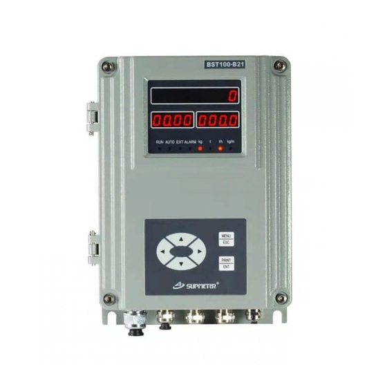
3.2 Model Wall-mounting Operation Interface RUN AUTO EXT ALARM kg kg/m MENU ▲ ◄ ► PRINT ▼ Display Panel A: kg, t, t/h, kg/m Display Panel B: g, kg, kg/h, g/m... -
Page 11: State Indication
3.3 State Indication LED Lamp Description Note ON: Weighing state. [RUN] OFF: Stopping state. Feeding control mode: [AUTO] ON: Auto [PID]. OFF: Manual. Flow Set Mode: [EXT] ON: External [AI: 4~20mA]. OFF: Internal. [ALARM] Alarm. [kg] Weight Display Unit: kg. Weight Display Unit: t. -
Page 12: Keypad Operation
3.4 Keypad Operation If there is not any keypad operation in one minute and it‟s not in the processes of „F2 Calibration‟ & „F6 Factory Adj.‟, the controller will return to „Main Display Interface‟ automatically. 3.4.1 Menu Operation Key Name Description 【MENU】... -
Page 13: Installation&Connection
4. Installation&Connection 4.1 Installation 4.1.1 Model Panel-mounting Installation (150) Outline dimension Panel dimension Cut dimension Installation Mode Outline dimension Panel dimension Box dimension Cut dimension W×H×D [mm] W×H [mm] W×H [mm] W×H [mm] 160×84×188 160×84 150×75 151×76... -
Page 14: Model Wall-Mounting Installation
4.1.2 Model Wall-mounting Installation Outline dimension stallation mode Outline dimension Mounting dimension Mounting hole dimension W×H×D [mm] W×H [mm] [mm] Ф9 202×305×90 169×271... -
Page 15: Terminal
4.2 Terminal 4.2.1 Model Panel-mounting Terminal DO/DI AO/AI/PO SENSOR ETHERNET COM1/2 POWER 4.2.2 Model Wall-mounting Terminal DO/DI AO/AI/PO COM1 COM2 LOADCELL SPEED DC12-24V OR AC220V SENSOR POWER... -
Page 16: Connection
4.3 Connection 4.3.1 Loadcell & Speed Sensor Connector (SENSOR) The shielded cable must be used and kept separate from the AC cable and other noise generating cables. Please use loadcells with the same capacity, bridge resistance & sensitivity (mV/V) for parallel connection. -
Page 17: Speed Sensor Connection (Sensor/Speed)
4.3.1.2 Speed Sensor Connection (SENSOR/SPEED) 4.3.1.2.1 Photoelectric Encoder Connection +5~12V Photoelectric Encoder Controller 4.3.1.2.2 Proximity Switch Connection Proximity Switch +5~12V 2-wire: VS+ will not be connected. Controller... -
Page 18: Speed Generator Connection
4.3.1.2.3 Speed Generator Connection +5~12V Speed Generator Controller 4.3.2 4~20mA Analog Output/Input & Totalized Weight Pulse Connector (AO/AI/PO) Max.3 definable AOs (4~20mA) are used for outputting „Flow/Control Current /…‟ signals to external devices. 1 Optional AI (4~20mA) is used for receiving „Flow Setpoint‟ signal from external devices. 1 High-speed Pulse [PO] is used for outputting Totalized Weight signal to external devices. -
Page 19: 20Ma Analog Output Connection (Ao)
4.3.2.1 4~20mA Analog Output Connection (AO) OUT+ AOx+ Load Isolator OUT- Max.500Ω AOx- Controller 4.3.2.2 4~20mA Analog Input Connection (AI) OUT+ Isolator Host OUT- Controller 4.3.2.3 Totalization Weight Pulse Output Connection (PO) Weight Per Pulse and Pulse Width can be set. 24VDC Receiver Pulse Input... -
Page 20: Switch Output/Input Connector (Do/Di)
4.3.3 Switch Output/Input Connector (DO/DI) 4 Definable normally open relay (AC250V/DC24V, 1A) or (DC24V, 500mA) switches are transistor used for outputting alarm/control signals to external devices. 3 Definable normally open switch inputs are used for receiving control signals from external devices. Description DO1+ Realy or Transistor Switch No.1 Output +/-. -
Page 21: Relay Switch Output (Do) To Load Connection
4.3.3.1 Relay Switch Output (DO) to Load Connection +24V Load DOx+ Spark Killer DOx- DOx+ Load Spark Killer AC220V DOx- Controller Load Circuit 4.3.3.2 Transistor Switch Output (DO) to Load Connection +24V DOx+ Load DOx- Controller Load Circuit... -
Page 22: Relay Switch Output (Do) To Plc Connection
4.3.3.3 Relay Switch Output (DO) to PLC Connection +24V DOx+ DOx- Switch input with common source Controller +24V DOx+ DOx- Controller Switch input with common ground... -
Page 23: Transistor Switch Output (Do) To Plc Connection
4.3.3.4 Transistor Switch Output (DO) to PLC Connection +24V DOx+ DOx- Controller Switch input with common source +24V +24V DOx+ DOx- Auxiliary Relay Controller Switch input with common ground... -
Page 24: Switch Input (Di) To Switch/Plc Connection
4.3.3.5 Switch Input (DI) to Switch/PLC Connection Switch or PLC with relay switch output OUT1.1 OUT1.2 OUT1 Switch output with common ground Controller +24V OUT1 Controller Auxiliary Relay Switch output with common source... -
Page 25: Digital Communication Port Connection (Com1/2)
4.3.4 Digital Communication Port Connection (COM1/2) COM1 Optional: RS232/RS485/RS422/Profibus-DP/CANBUS/Ethernet modules. COM2: RS232. Connectable: IPC/PLC, Remote Display&Operation Terminal, Serial Printer and Wireless Module. 4.3.4.1 Model Panel-mounting Communication Port COM1 COM2 RS485 RS422 RS232 Profibus-DP RS232 CANBUS Ethernet TXD- TXD+ DP- (B) RXD+ RXD- DP+ (A) -
Page 26: Rs232 To Ipc/Plc Host-Slave&Point-To-Point Network
4.3.4.3 RS232 to IPC/PLC Host-slave&Point-to-point Network Host (IPC/PLC) Max. transmission distance: 15m. TXD RXD GND Communication mode: Host-slave. RXD GND Slave: Controller 4.3.4.4 RS232 to Printer, Remote Display&Operation Terminal Point-to-point Network Controller Max. transmission distance: 15m. Communication mode: TXD RXD GND ... -
Page 27: Rs485/Canbus/Profibus-Dp To Ipc/Plc Host-Slave Data-Bus Network
4.3.4.5 RS485/CANBUS/Profibus-DP to IPC/PLC Host-slave Data-bus Network Host (IPC/PLC) Terminal resistor R=120~150Ω. RS485 max. transmission distance: 1200m. Communication mode: RS485/CANBUS: Host-slave. Profibus-DP: DP-Modicon/DP-Siemens. … … N≤31 Slave: Controller 4.3.4.6 RS485 to Remote Display&Operation Terminal Point-to-point Network Controller ... -
Page 28: Rs422 To Ipc/Plc Host-Slave Data-Bus Network
4.3.4.7 RS422 to IPC/PLC Host-slave Data-bus Network Host (IPC/PLC) TXD- TXD+ RXD+ RXD- GND Terminal resistor R=120~150Ω. Max. transmission distance: 1200m. Communication mode: Host-slave. TXD- TXD+ RXD+ RXD- GND Slave: Controller #1~N, N≤31 4.3.4.8 Ethernet Host-slave Network Host ... -
Page 29: Power Supply Connector (Power)
4.3.5 Power Supply Connector (POWER) Please make sure that the power supply is correct before power-on. If the voltage fluctuation exceeds the allowable range, please use regulated power supply. Description Voltage Null Wire. Earth Wire. AC220V± 15%. Live Wire. Description Voltage DC Input -. -
Page 30: Operation Procedure
5. Operation Procedure Connection & Power on „Speed Coeff.‟ & „Belt Length‟ Setting (Scale Setting) Zero Calibration Dynamic Span Calibration Or Static Span Calibration „Weighing Dead Band‟ Setting (Scale Setting) I/O Setting Serial Port Setting Control Setting (Used for belt feeder) Other Settings Key-Locking... -
Page 31: Function&Operation
6. Function&Operation The following display&operation interfaces are described with „kg‟ as the Internal Scale Unit. If the parameter „[P107] Internal Scale Unit‟ is set to „g‟, the actual Weight Display Unit will be different. 6.1 Main Display Interface 【▲】 【▼】: Display the next/previous interface. 6.1.1 Totalized Weight, Belt Speed &... -
Page 32: Flow & Control Current
6.1.3 Flow & Control Current RUN AUTO EXT ALARM kg/m 【◄】 【►】: Control Current Iout ± 1mA 【ENT】: Set „Control Current‟ value RUN AUTO EXT ALARM kg/m 6.1.4 Totalized Weight, Load Setpoint & Load RUN AUTO EXT ALARM kg/m Load=Flow / (3.6× Speed) Load Setpoint=Flow Setpoint / (3.6×... -
Page 33: Alarm Items
6.1.5 Alarm Items RUN AUTO EXT ALARM kg/m ALr- Alarm Count 【ENT】: Alarm Query RUN AUTO kg/m EXT ALARM 【▲】 【▼】: Query Switch; 【MENU】: Exit Sign Alarm Item Alarm Condition Flow ≥ Flow Range × Flow Upper Limit(%) FLou -HI- Flow Upper Limit Flow ≤... -
Page 34: Other Display Interface
6.1.6 Other Display Interface The Numeric Display 1 displays Totalized Weight value and the Numeric Display 2-3 displays the following data: Display iterms Sign Range Totalized Weight 0~999999 Current Batch AD Value 0~65535 Zero Value 0~60000 9~11 DI State dI1-/dI2-/dI3- -oFF/-on- 12~15 DO State... -
Page 35: Main Menu
6.2 Main MENU Main Menu Second Menu Description --SCAL-- Basic scale parameters setting. --SCAL1- Extra scale parameters setting. --CtrL-- Basic feeding control parameters setting. --CtrL1- Extra feeding and batching control parameters setting. --Flou-- Flow parameters setting. ≡F1-SEt≡ --SPEd- Speed parameters setting. Setting --LoAd-- Load parameters setting. - Page 36 Main Menu Second Menu Description Clear Screen: Clear Totalized Weight and Totalized Weight Pulse Count. ---CLS-- But Totalized Weight of Current Shift will not be cleared, so this operation has no effect on recording of weight per shift. Clear Weight: Clear Totalized Weight, Totalized Weight Pulse Count and ≡F4-CLS≡...
-
Page 37: F1-Set Setting
6.3 F1-SET Setting 6.3.1 Basic Scale Parameters (SCAL) Sign Parameter Range Default 0: kg 1: t ([P107] Scale Unit = kg) P100 UnIt Weight Display Unit 0: g 1: kg ([P107] Scale Unit = g) 0: o 1: o.o P101 -dot Weight Decimal Point 2: o.oo... -
Page 38: Extra Scale Parameters (Scal1)
6.3.2 Extra Scale Parameters (SCAL1) Sign Parameter Range Default P110 -Cn- Calibration Revolutions 1~99R (1R=1 Belt Length) 0.1~1000.0kg/m ([P107] Scale Unit = kg) Chain Weight for Span Calibration P111 CHAn Chain Weight 10.0 0.1~1000.0g/m ([P107] Scale Unit = g) 0.1~1000.0kg ([P107] Scale Unit = kg) Hanging Weight for Span Calibration P112... -
Page 39: Basic Control Parameters (Ctrl)
6.3.3 Basic Control Parameters (CtrL) Sign Parameter Range Default 0.00~5000.00t/h ([P107] Scale Unit = kg) P200 SEtF Flow Setpoint 20.00 0.00~5000.00kg/h ([P107] Scale Unit = g) 0.1~5000.0 A bigger P value indicates a higher-precision P201 --P- P Value 100.0 feeding adjustment but a longer time for flow to reach the target value [Flow Setpoint]. -
Page 40: Extra Control Parameters (Ctrl1)
6.3.4 Extra Control Parameters (CtrL1) Sign Parameter Range Default Initial Current P210 PIdL 0.0-999.9s Hold Time 0: Present (Present Current Value) P211 InIC PID Initial Current 1: Fuzzy (Fuzzy Current Value) 2: Set [P219] (Set Value of [P219]) 0.01~100.00 [t/h]/mA ([P107] Scale Unit = kg) Flow Increment per Increasing 1mA P212... -
Page 41: Flow Parameters (Flou)
6.3.5 Flow Parameters (Flou) Sign Parameter Range Default 0: t/h 1: kg/min 2: kg/h ([P107] Scale Unit = kg) P300 UnIt Flow Display Unit 0: kg/h 1: g/min 2: g/h ([P107] Scale Unit = g) P301 -dot Flow Decimal Point 0: o;... -
Page 42: Speed Parameters (Sped)
6.3.6 Speed Parameters (SPEd) Sign Parameter Range Default 0: o 1: o.o P400 -dot Speed Decimal Point 2: o.oo 3: o.ooo P401 rAng Speed Range 0.100~5.000m/s 3.000 P402 -HI- Speed Upper Limit (0.0~100.0)% Speed Range 100.0% P403 -Lo- Speed Lower Limit (0.0~100.0)% Speed Range 0.0% P404... -
Page 43: Load Parameters (Load)
6.3.7 Load Parameters (LoAd) Sign Parameter Range Default 0: o P500 -dot Load Decimal Point 1: o.o 2: o.oo 0.01~5000.00kg/m ([P107] Scale Unit = kg) P501 rAng Load Range 100.00 0.01~5000.00g/m ([P107] Scale Unit = g) P502 -HI- Load Upper Limit (0.0~100.0)% Load Range 100.0% P503... -
Page 44: Communication Parameters (Serp)
6.3.9 Communication Parameters (SErP) Sign Parameter Range Default P700 -Adr Communication Address 00~99 0: 1200bps 1: 2400bps P701 bPS1 COM1 Baud Rate 2: 4800bps P702 bPS2 COM2 Baud Rate 3: 9600bps 4: 19200bps 5: 115200bps 0: None P703 CHC1 COM1 Parity Check 1: Even P704 CHC2... -
Page 45: I/O Parameters (-Io-)
6.3.10 I/O Parameters (-Io-) Sign Parameter Range Default 0: None 1: Flow 2: Control Current 3: Load 4: Speed P800 -Ao1 AO1 Signal 5: From AI [4~20mA] P801 -Ao2 AO2 Signal 6: From Communication Port P802 -Ao3 AO3 Signal 7: Totalized Weight High-speed Pulse (4mA→ 20mA→4mA) 8: Totalized Weight Low-speed Pulse (4mA→... - Page 46 Sign Parameter Range Default 0: None 1: Weighing (ON: Weighing; OFF: No Weighing) 2: PID Start (ON: Start PID; OFF: Stop PID) 3: Sys. Ready (ON: System Ready, DI.Start Signal is valid) 4: Zero Calibration (OFF→ON→OFF) 5: Clear Screen (OFF→ON→OFF) P807 -dI1 DI1 Signal...
-
Page 47: Display Parameters (Disp)
6.3.11 Display Parameters (dISP) Sign Parameter Range Default 0: Chinese 1: English P900 LAng Printing Language 0/1[*] * „RAM Reset‟ operation has no effect on this parameter. P901 dSPt Display Refreshing Time 0.1~2.0s 5~15 LED Brightness While * „RAM Reset‟ operation has no P902 runL 10[*]... -
Page 48: A Sample Of Parameter Setting
6.3.13 A Sample of Parameter Setting Modify the parameter „[P103] Speed Coefficient‟. Main Display Interface 【MENU】+【▲】 【▼】 RUN AUTO EXT ALARM kg/m 【ENT】+【▲】 【▼】 RUN AUTO kg/m EXT ALARM 【ENT】+【▲】 【▼】 RUN AUTO EXT ALARM kg/m 【ENT】+【▲】 【▼】 RUN AUTO EXT ALARM kg/m 【◄】... -
Page 49: F2-Cal System Calibration
6.4 F2-CAL System Calibration 6.4.1 Zero Calibration (ZEro) Keep the belt weigher running without load for correcting Zero Value. Main Display Interface 【MENU】+【▲】 【▼】: ≡F2-CAL≡ 【ENT】+【▲】 【▼】: --ZEro-- 【ENT】 RUN AUTO kg/m EXT ALARM Input Calibration Revolutions 【ENT】 RUN AUTO EXT ALARM kg/m Zr: Zero Value... -
Page 50: Dynamic Span Calibration (Load)
6.4.2 Dynamic Span Calibration (LoAd) Let the belt weigher run with loading measured materials or Poise Weights for correcting Span Coefficient. Main Display Interface 【MENU】+【▲】 【▼】: ≡F2-CAL≡ 【ENT】+【▲】 【▼】: --LoAd-- 【ENT】& Start loading AUTO kg/m EXT ALARM Totalized Weight; Revolution Count & Remainder length of a revolution (【▲】... - Page 51 RUN AUTO EXT ALARM kg/m Input Calibrating Weight [kg] 【ENT】 RUN AUTO kg/m EXT ALARM 【MENU】: Exit 【ENT】: Save...
-
Page 52: Static Span Calibration With Chain Weight (Chan)
6.4.3 Static Span Calibration with Chain Weight (CHAn) Keep the belt weigher running with loading a chain weight for correcting Span Coefficient. Put a measured chain weight as a continuous and steady load on the belt weigher and then start the belt weigher. - Page 53 RUN AUTO EXT ALARM kg/m 【ENT】 RUN AUTO EXT ALARM kg/m Input Calibrating Weight [kg] = Calibration Revolutions × Belt Length × Chain Weight 【ENT】 RUN AUTO kg/m EXT ALARM 【MENU】: Exit 【ENT】: Save...
-
Page 54: Static Span Calibration With Hanging Weight (Hang)
6.4.4 Static Span Calibration with Hanging Weight (HAng) Keep the belt weigher running with loading hanging weights for correcting Span Coefficient. Put a measured hanging weight as a steady load on the belt weigher and then start the belt weigher. Main Display Interface 【MENU】+【▲】... - Page 55 AUTO EXT ALARM kg/m Totalized Weight; Revolution Count & Remainder length of a revolution (【▲】 【▼】: Display Flow or AD value) After running the last revolution RUN AUTO kg/m EXT ALARM 【ENT】 RUN AUTO kg/m EXT ALARM Input Calibrating Weight [kg] = Calibration Revolutions × Belt Length ×...
-
Page 56: Segmenting Span Correction (Segc)
6.4.5 Segmenting Span Correction (SEgC) After doing Dynamic or Static Span Calibration, further corrections for 3 [AD Value: 0~60000] linear segments are optional for correcting Correction Coefficient 1~3. Main Display Interface 【MENU】+【▲】 【▼】: ≡F2-CAL≡ 【ENT】+【▲】 【▼】: --SEgC-- 【ENT】 RUN AUTO kg/m EXT ALARM AD Value Linear Segment: 1~3;... - Page 57 RUN AUTO EXT ALARM kg/m 【ENT】 RUN AUTO EXT ALARM kg/m Input Calibrating Weight [kg] 【ENT】 RUN AUTO kg/m EXT ALARM [P121]/[P122]/[P123] Span Correction Coefficient: 0.500~2.000 【MENU】: Exit 【ENT】: Save...
-
Page 58: Speed Calibration (Sped)
6.4.6 Speed Calibration (SPEd) Keep the belt weigher running at a constant speed. After the belt running time of a revolution being measured by stopwatch, do this operation for correcting Speed Coefficient. Main Display Interface 【MENU】+【▲】 【▼】: ≡F2-CAL≡ 【ENT】+【▲】 【▼】: --SPEd-- 【ENT】... -
Page 59: Belt Length Calibration (Lens)
6.4.7 Belt Length Calibration (LEnS) Keep the belt weigher running at a constant speed. After the belt running time of a revolution being measured by stopwatch, do this operation for correcting Belt Length. Main Display Interface 【MENU】+【▲】 【▼】: ≡F2-CAL≡ 【ENT】+【▲】 【▼】: --LEnS-- 【ENT】... -
Page 60: F3-Rec Weight Record For Querying&Printing
6.5 F3-REC Weight Record for Querying&Printing Weight records per shift/day/month of a year can be queried and printed. Main Display Interface 【MENU】+【▲】/【▼】: ≡F3-REC≡ 【ENT】 RUN AUTO kg/m EXT ALARM Input Date 【ENT】 RUN AUTO kg/m EXT ALARM Totalized Weight of a Shift, YY.MM.DD-Shift No.1~4 【◄】... - Page 61 RUN AUTO kg/m EXT ALARM Totalized Weight from the first day of this month to this day, 【PRINT】: Print weight records (See Appendix A.Table 3) 【MENU】...
-
Page 62: F4-Cln Data Clearing
6.6 F4-CLn Data Clearing Main Display Interface 【MENU】+【▲】 【▼】: ≡F4-CLn≡ 【ENT】+【▲】 【▼】: ---CLS-- 【ENT】 CLS: Clear Screen; CLt: Clear Weight; CLr : Clear Records RUN AUTO kg/m EXT ALARM 【▲】 【▼】 :YES/NO 【MENU】: Exit 【ENT】: Enter Data Clearing Mode Description: ... -
Page 63: F5-Saf Security
6.7 F5-SAF Security 6.7.1 Auto-locking (ALoc) Main Display Interface 【MENU】+【▲】 【▼: ≡F5-SAF≡ 【ENT】+【▲】 【▼】: --ALoc-- 【ENT】+ Input Password +【ENT】 RUN AUTO EXT ALARM kg/m 【▲】 【▼】: 0[OFF] / 1[ON] 【MENU】: Exit 【ENT】: Enter Auto-locking: If there is not any keypad operation in one minute and it‟s not in the processes of „F2 Calibration‟ & „F6 Factory Adj.‟, the controller will lock the keypad and return to „Main Display Interface‟... -
Page 64: Key-Unlocking (Open)
6.7.3 Key-unlocking (oPEn) Main Display Interface 【MENU】+【▲】 【▼】: ≡F5-SAF≡ 【ENT】+【▲】 【▼】: --oPEn-- 【ENT】 RUN AUTO kg/m EXT ALARM Input Password 【MENU】: Exit 【ENT】: Enter... -
Page 65: Password Set (Pass)
6.7.4 Password Set (PASS) Main Display Interface 【MENU】+【▲】 【▼】: ≡F5-SAF≡ 【ENT】+【▲】 【▼】: --PASS-- 【ENT】 RUN AUTO kg/m EXT ALARM Input Original Password 【ENT】 RUN AUTO kg/m EXT ALARM Please input and remember the new password 【MENU】: Exit 【ENT】: Save... -
Page 66: Ram Reset (Defu)
6.7.5 RAM Reset (dEFU) Main Display Interface 【MENU】+【▲】 【▼】: ≡F5-SAF≡ 【ENT】+【▲】 【▼】: --dEFU-- 【ENT】 RUN AUTO kg/m EXT ALARM 【▲】 【▼】: YES/NO 【MENU】: Exit 【ENT】: Enter 6.8 F6-FAC Factory Adjustment Only after Key-unlocking with the Factory Password, this operation will be valid. 6.8.1 AO Zero Adjustment (AoxE) Main Display Interface 【MENU】+【▲】... -
Page 67: Ao Full Range Adjustment (Aoxf)
6.8.2 AO Full Range Adjustment (AoxF) Main Display Interface 【MENU】+【▲】 【▼】: ≡F6-FAC≡ 【ENT】+【▲】 【▼】: AoxF(x=1~3) 【ENT】 RUN AUTO kg/m EXT ALARM Set AOx Full value (2000~4095) to make AOx output 20.00mA. 【MENU】: Exit 【ENT】: Save 6.8.3 AI Zero Adjustment (AI1E) Main Display Interface 【MENU】+【▲】... -
Page 68: Ai Full Range Adjustment (Ai1F)
6.8.4 AI Full Range Adjustment (AI1F) Main Display Interface 【MENU】+【▲】 【▼】: ≡F6-FAC≡ 【ENT】+【▲】 【▼】: AI1F 【ENT】 RUN AUTO kg/m EXT ALARM Input 20.00mA from AI port to correct AI full value (2000~4095) 【MENU】: Exit 【ENT】: Save 6.9 F7-InF Product Information Main Display Interface 【MENU】+【▲】... -
Page 69: Ration Flow Auto-Feeding System
7. Ration Flow Auto-Feeding System Feeder Loadcell Belt Weigher Speed Sensor Summing Box Frequency Convertor & Relays DI/DO/AO: Definable. AO3: If you need it, inform us in your order. AO.Corntrol Current AO.Corntrol Current Diverter Switch DI. System Ready DO.Feeder Control Controller DI. -
Page 70: Appendix A. Print Formats
Appendix A. Print Formats Print Format A: Table 1. Weight Record For A Shift (SW) Table 3. Weight Record For A Month (MW) WEIGHT RECORD WEIGHT RECORD -------------------------- -------------------------- DATE: 2009-05-20 DATE: 2009-05-01 NAME: NAME: 109980kg 387090kg -------------------------- DATE: 2009-05-02 2009-05-20 23:59 NAME:... -
Page 71: Appendix B. Communication Protocols
Print Format B: Table 1. Weight Record For A Shift (SW) WEIGHT RECORD -------------------------------------------------- DATE NAME WEIGHT 2009-05-20 109980kg -------------------------------------------------- 2009-05-20 23:59 Table 2. Weight Record For A Day (DW) WEIGHT RECORD -------------------------------------------------- DATE NAME WEIGHT 2009-05-20 109980kg 2009-05-20 169900kg 2009-05-20... - Page 72 User’s Memo...
- Page 73 Changsha Supmeter Technological Co.,Ltd. Address: Building A6, Lugu International Industrial Park, Changsha, 410205, China Tel: +86 731 85115100 Fax: +86 731 85158100 Website: www.supmeter.com.cn E-mail: supmeter@163.com...
Need help?
Do you have a question about the BST100-B11 and is the answer not in the manual?
Questions and answers