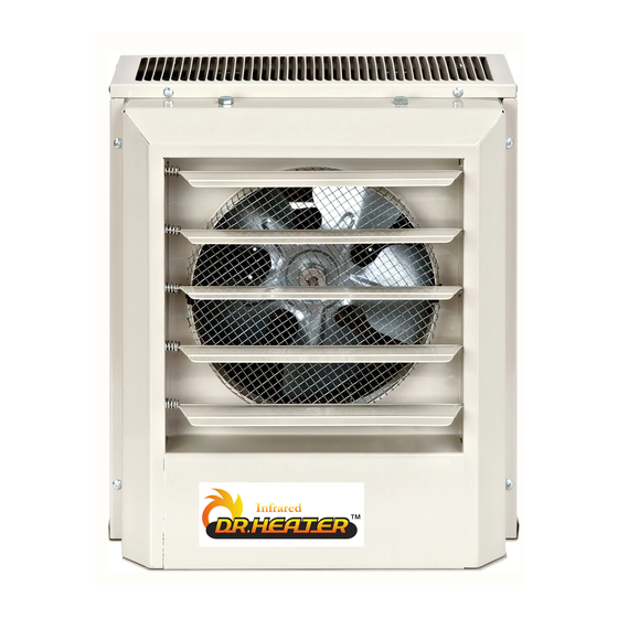
Summary of Contents for DR. Heater DR-P130
- Page 1 Heavy-Duty Electric Unit Heaters OWNER’S MANUAL Model: DR-P130 DR-P350 DR-P275 DR-P2100 DR-P3150 DR-P3200 IMPORTANT INSTRUCTIONS READ & SAVE...
-
Page 2: Important Instructions
IMPORTANT INSTRUCTIONS PLEASE READ ALL INSTRUCTIONS BEFORE USING THIS HEATER NOTE: There may be a trace of smoke or odor when unit is first operated. Don’t be alarmed. This indicates that a drop of oil fell on the heating coil during the manufacturing process. It will quickly evaporate and should not re-occur. -
Page 3: Specifications
Heater/ Amps Temp BTU/HR Control CFM at FPM at Model Motor Phase Rise 1000’S Voltage Outlet Outlet Voltage Phase (℉) DR-P130 10.2 14.5 1/100 1600 DR-P350 1/100 1600 DR-P275 25.6 1 or 3 1/30 1600 10.0/ 42.0/ DR-P2100 34.1/25.6 240/208... -
Page 4: Installing Instructions
INSTALLING INSTRUCTIONS All wiring must be installed by a certified electrician according to the electrical safety. The ceiling heater must be grounded in accordance with all national and local building codes. All wiring procedures and connections shall be in accordance with the national and local codes having jurisdiction. - Page 5 MOUNTING ROD MOUNTING HORIZONTAL DISCHARGE 1 Install four threaded mounting rods in the threaded holes and secure in place using lock nuts. 2 Securely attach the four mounting rods to the ceiling. (Refer to Table 1 for wall and ceiling clearances, and Table 2 for mounting rod spacing) Mounting Rod(4)
- Page 6 4 A knockout is provided in the back of the heater close to the power terminal board. The control terminal board knockout is 1/2 inch conduit size. The power terminal block knockout is multiple diameter. Use the diameter that fits the required conduit size. For model DR-P130 and DR-P350 knockout here Trade...
- Page 7 M5X1.0 DR-P350 M6X1.0 DR-P275 M6X1.0 DR-P2100 M6X1.0 DR-P3150 M6X1.0 DR-P3200 6 The power terminal board is equipped with box terminals sized to accept the correct size power supply wire. Wire rated at 600V and 60°C is satisfactory for the heater branch circuit. Copper wire is satisfactory for connection to the heater power terminal board box terminal.
-
Page 8: Control Wiring
CONTROL WIRING Line voltages is present on some of the terminals on the control terminal board. Always disconnect the power from the heater before making any connections to the control board to prevent hazard. 1.Use min. 600 volt, NEC Class 1 insulated wire for all control circuit wiring. 2.Use a crimp-on type fork terminal on the wire ends that attach to the control terminal board if more than one connection is to be made under the terminal screw. - Page 9 Wiring Diagrams DR-P130 DR-P350...
- Page 10 DR-P2100 DR-P275...
- Page 11 DR-P3150&DR-P3200...
-
Page 12: Troubleshooting
TROUBLE SHOOTING If your heater fails to operate, please follow these procedures: This heater has a thermal cut-off protection. If the thermal cut-off protection trips, switch off the power, switch off the circuit breaker. The unit should reset automatically after 10-30 minutes. If the thermal cut-off protection trips again, consult a certified/licensed electrician to determine the reason for overheating. - Page 13 Let us know with a customer review. https://www.amazon.com/review/review-your-purchases# Please visit: Dr. Heater USA, we are committed to bringing top quality alternative & supplemental heating products to our customers. Dr. Heater USA 9293 Beatty Dr, Sacramento, CA 95826 Tel: 1-800-317-1688 EMAIL: SERVICE@DRHEATERUSA.COM...


Need help?
Do you have a question about the DR-P130 and is the answer not in the manual?
Questions and answers