
Related Manuals for DR. Heater DR-PS11024


Summary of Contents for DR. Heater DR-PS11024
- Page 1 Salamander Heater der Heater OWNER’S MANUAL Model:DR-PS11024 10KW 240V 60Hz 1P 10KW 240V 60Hz 1P DR-PS11524 15KW 240V 60Hz 1P 15KW 240V 60Hz 1P DR-PS31520 15KW 208V 60Hz 3P 15KW 208V 60Hz 3P IMPORTANT INSTRUCTIONS IMPORTANT INSTRUCTIONS READ & SAVE...
-
Page 2: Table Of Contents
TABLE OF CONTENTS Important Instructions………………………………………...3-4 Parts of the Heater ……………………….……………………5 Installing Instructions……………………….…………..…….6-9 Specifications and Wiring Diagram………………………. ..10-14 Operating Instructions……………………….………..……..15 Maintenance and Cleaning……………………………………16 Warranty Information ………………………………………….17 ARRANTY INFORMATION... -
Page 3: Important Instructions
IMPORTANT INSTRUCTIONS PLEASE READ ALL INSTRUCTIONS BEFORE USING THIS HEATER NOTE: There may be a trace of smoke or odor when unit is first operated. Don’t be alarmed. This indicates that a drop of oil fell on the heating coil during the manufacturing process. It will quickly evaporate and should not re-occur. -
Page 4: Save These Instructions
10) Do not insert or allow foreign objects to enter any ventilation or exhaust opening as this may cause an electric shock or fire, or damage the heater. 11) To prevent a possible fire, do not block air intakes or exhaust in any manner. -
Page 5: Parts Of The Heater
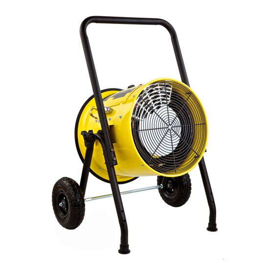
PARTS OF THE HEATER Handle Heater Housing C. Tilt adjustable knob D. Wheel Front Grill ON/OFF Switch G. Temperature Setting Knob... -
Page 6: Installing Instructions
Before installation: Disconnect the main supply connection. DR-PS11024, the heater must be connected to an individual branch circuit protected by a 55 Amp circuit breaker. Supply cables must be equipped with a dual pole circuit breaker rated at least 240V 55A/pole as the main cutoff switch of power to the heater. -
Page 7: Installation Instructions
INSTALLATION INSTRUCTIONS: 1. Open the package; take out the heater and the foot stand parts. The parts list as below: Item Spec Quantity No. Item Spec Quantity Axle Washer Φ8 Handle Screw M8X80 Foot Stand Screw M6X55 Wheel Washer Φ6 Axle Sleeve M6X20 Knob... - Page 8 2. Use axle (item 1), axle sleeve (item 5), and washer (item 7) to assemble the foot stand and the wheels as shown below: 3. Tighten the nuts (item 6) to the wheels as shown below: 4. Use the screw (item 10), washer (item 9), and nut (item 8) to assemble the handle to the foot stand as shown below.
- Page 9 5. Use the rubber pad (item 16), washer (item 15), and the knobs (item 14) to assemble the heater to the foot stand. Tighten the knobs as shown below: 6. Insert the screws (item 11) and the nuts (item 13) to the location hole of the foot stand.
-
Page 10: Specifications And Wiring Diagram
SPECIFICATIONS Salamander Heater with cart Model: DR-PS11024 Volt: 240V, 1P Watts: 10KW Frequency: 60 Hz Wiring diagram: DR-PS11024... - Page 11 Model: DR-PS11524 Volt: 240V, 1P Watts: 15KW Frequency: 60 Hz Wiring diagram: DR-PS11524...
- Page 12 Model: DR-PS31520 Volt: 208V, 3P Watts: 15KW Frequency: 60 Hz Wiring diagram: DR-PS31520...
- Page 13 WIRING INSTRUCTIONS INSTRUCTIONS For 1 Phase Model: PS-10241, PS-15241 1. Open the wiring cover: 2. Connect the black live wire to L1, white live wire to L2 of the terminal live wire to L2 of the terminal block. L2 White Wire L1 Black Wire 3.
- Page 14 For 3 Phase Model: DR-PS31520 1. Open the wiring cover: 2. Connect the red live wire to L1, black live wire to L2, and the white live wire to L1, black live wire to L2, and the white live wire to L3 of the connector. L3: White Live Wire L2: Black...
-
Page 15: Operating Instructions
OPERATING INSTRUCTIONS WARNING - The heater must be properly installed before it is used. HAZARD OF ELECTRIC SHOCK, EXPLOSION, OR ARC FLASH : Apply appropriate personal protective equipment (PPE) and follow safe electrical work practices. See NFPA 70E. A circuit breaker must be installed and serviced only by qualified electrical personnel. -
Page 16: Maintenance And Cleaning
MAINTENCE AND CLEANING No user maintenance on this heater should be undertaken except regular cleaning as described below. All other servicing or maintenance should be performed by qualified service personnel. Before any cleaning, make sure that: 1. Power supply is disconnected at the source. 2. -
Page 17: Warranty Information
WARRANTY. If your unit does not appear to be working properly, please contact our service center by calling 1-800-317-1688. Dr. Infrared Heater 239 Harbor Way SOUTH SAN FRANCISCO, CA 94080 TEL: 800-317-1688 EMAIL: SERVICE@DRHEATERUSA.COM SERVICE@DRHEATERUSA.COM Dr Heater USA @DrHeaterUSA Dr. Heater USA Dr. Heater USA...
Need help?
Do you have a question about the DR-PS11024 and is the answer not in the manual?
Questions and answers