
Subscribe to Our Youtube Channel
Related Manuals for DR. Heater DR-368


Summary of Contents for DR. Heater DR-368
- Page 1 Carbon Infrared Heater Indoor/Outdoor Ceiling-Mount and Wall-Mount Owner’s Manual Model No.: DR-368...
-
Page 2: Important Instructions
Warning THESE INSTRUCTIONS SHOULD BE READ CAREFULLY AND RETAINED FOR FUTURE REFERENCE, We cannot be liable for any damages caused by failure to observe these instructions. IMPORTANT INSTRUCTIONS READ CAREFULLY-The infrared heater is designed for safe operation. Nevertheless, installation, maintenance and operation of the heater can be dangerous. - Page 3 18. This heater is not intended to be used in bathrooms, laundry areas, and similar indoor areas. Never put a heater where it may fall into a bathtub or other water container. 19. No liability can be accepted for any damage caused by non-compliance with these instructions or any other improper use or mishandling.
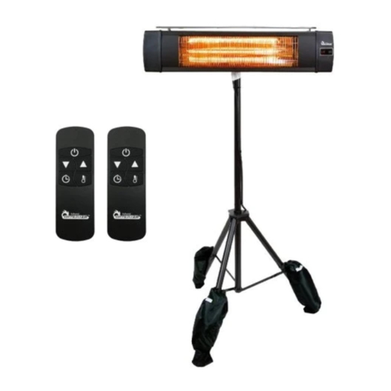
- Page 4 Introduction The DR-368 carbon infrared heater produces instant and comfortable heat like the sun. This heater is designed for both indoor and outdoor areas. Model DR-368 Voltage(V) 120V AC Wattage(W) 1500W Hertz (Hz) Dimensions W×H×D(in.) 34.6 x 7.69 x 3.33 Weight (lb) This heater is designed for 120 volts AC input.
-
Page 5: Product Features
Product Features CLEAN AND INSTANT HEAT with 3 POWER SETTING Clean, instant, and odorless infrared heat with 3 power settings, 900W, 1200W, 1500W. 120V, 60Hz. HIGH-EFFICIENCY REFLECTOR AND CARBON INFRARED ELEMENT Precision mirror aluminum reflector with 90% reflection efficiency. Carbon infrared elements heat the person but not the object, which is ideal for patio heating. -
Page 6: Installation
INSTALLATION A mounting bracket is provided with the heater which has been specifically designed to allow this product to be fitted to ceiling or wall before drilling the holders for the ceiling/wall is solid and that there are no hidden water pipes or electric wires. ATTENTION! The appliance must be installed on the solid surfaces like concrete, wood or metal etc. - Page 7 Remove the heater from the tripod stand The ceiling/wall mount will reuse part of the hardware from the tripod mount installation. Follow the steps below to remove the heater from the tripod stand. Installing heater out of the box on to ceiling or wall, skip the protection bracket removal steps.
- Page 8 3. After removed the protection bracket, tighten the screws from Step 2 back on the top of the heater using the screwdriver as shown in Fig - 3. Tighten 2 screws Fig - 3 4. Take off the long screw (H7) with wing nut (H6) as shown in Fig - 4 Fig - 4 5.
- Page 9 6. Take off the hand-tight screw and the wing nut that’s already installed on the stand. Disassemble and remove the U-shaped bracket (H9) from the stand as shown in Fig - 6. Keep the U-shaped brackets for later installation steps. Wing Nut U-shaped bracket Take off...
- Page 10 Ceiling or Wall Mount Instruction Required hardware contents Desc. Desc. L shaped bracket Wing Nut Plastic anchor Long Screw Screw Bracket U shaped Bracket Screw Heater Heater with H8 bracket Page...
- Page 11 1. Take off the screw on the heater and slide protective cover to disable tip over switch as show in Fig-1a. PRESS the switch to disable the tip over function as show in Fig-1b.Tighten back the screw on the heater as show in Fig-1c. Fig - 1a Fig - 1b Fig - 1c...
- Page 12 3. Mark the locations using the provided dimensions in Fig - 3a and using the holes on the L-bracket as a guide. Ceiling and Wall Mounting Height: maintain at least 2.4m / 94.5” distance between the heater and the floor. Fig - 3a 4.
- Page 13 6. Using a screwdriver mount the assembled L-shaped bracket (H1) to the anchors using screws (H3) as shown in Fig - 6a. H3 H3 H3 H3 Fig - 6a 7. Hanging the heater’s bracket on the U-shaped bracket as shown in Fig-7a. Fasten the long screw (H7) with wing nuts (H6) as shown in Fig - 7b.
- Page 14 8. Mounting Height: maintain at least 2.4m / 94.5” distance from the heater to the ground as shown in Fig - 8a. m / 94.5” Min 2.4 Fig - 8a Mounting height at least 2.4m / 94.5” Attention: cable should not pass through the heater 13 | Page...
-
Page 15: Function And Operation
FUNCTION & OPERATION OPERATING Operating unit with built-button 1. Apply power to the heater. The heater will be on standby mode display (- -) on LED screen. 2. Press the button on the unit to cycle through the functions, heat levels (L1-L2-L3), standby, and off. - Page 16 PUSH BUTTON: The heater can be manually operated without the remote control. Use the button on the right side of the heater to cycle to operation modes, Standby, Heat Level (L1, L2, L3). PUSH BUTTON Heat Level (L1) Heat Level (L2) Standby (- -) Heat Level (L3) Standby (- -)
-
Page 17: Troubleshooting
Troubleshooting 1. Check if the power cord is plugged into an electrical outlet, if not, plugged in. 2. Check if the electricity to the main fuse is working 3. Error code shows on the display. E1: Control unit over-temperature protection. Check installation clearances. Let the heater cool for 15 minutes and restart the heater. - Page 18 Storage: Store the heater in a cool, dry location when not in use to prevent dust and dirt build-up. Wrap the power cord with ties. Use packaging cartons to store. ATTENTION: Always disconnect the heater from the electrical power source and allow it to cool down before attempting to work on it.
- Page 19 Register your product at our website: Or visit DrHeaterUSA.com/register-your-heater At Dr. Heater USA, we are committed to bringing top-quality alternative & supplemental heating products to our customers. Note: There may be a trace of smoke or odor when the unit is first operated. Do not be alarmed. This indicates a drop of oil fell on the interior coils during the manufacturing process.
Need help?
Do you have a question about the DR-368 and is the answer not in the manual?
Questions and answers