Advertisement
Quick Links
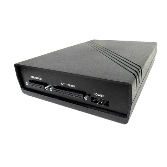
RS-232 ↔ RS-485 Interface Converter
CUSTOMER
SUPPORT
INFORMATION
D S R C T S
Order toll-free in the U.S. 24 hours, 7 A.M. Monday to midnight Friday: 877-877-BBOX
FREE technical support, 24 hours a day, 7 days a week: Call 724-746-5500 or fax 724-746-0746
Mail order: Black Box Corporation, 1000 Park Drive, Lawrence, PA 15055-1018
Web site: www.blackbox.com • E-mail: info@blackbox.com
P W R
D A T A
SEPTEMBER 1993
IC485A-R2
IC485C-R2
4 8 5
2 3 2
D A T A
D S R C T S
Advertisement

Related Manuals for Black Box IC485A-R2


Summary of Contents for Black Box IC485A-R2
- Page 1 Order toll-free in the U.S. 24 hours, 7 A.M. Monday to midnight Friday: 877-877-BBOX FREE technical support, 24 hours a day, 7 days a week: Call 724-746-5500 or fax 724-746-0746 SUPPORT Mail order: Black Box Corporation, 1000 Park Drive, Lawrence, PA 15055-1018 INFORMATION Web site: www.blackbox.com • E-mail: info@blackbox.com...
- Page 2 RS-232 ↔ RS-485 INTERFACE CONVERTER FEDERAL COMMUNICATIONS COMMISSION RADIO FREQUENCY INTERFERENCE STATEMENT This equipment generates, uses, and can radiate radio frequency energy and if not installed and used properly, that is, in strict accordance with the manufacturer's instructions, may cause interference to radio communication.
-
Page 3: Table Of Contents
RS-232 ↔ RS-485 INTERFACE CONVERTER Contents 1.0 SPECIFICATIONS..........................4 2.0 INTRODUCTION..........................5 3.0 INSTALLATION..........................7 Jumpers and DIP Switches....................7 Select DTE/DCE Operation ....................7 Physical Installation.......................7 Indicators..........................11 Interface Pinouts .........................14... -
Page 4: Specifications
115 VAC power supply: ±10%, 100 mA rms Power — 230 VAC power supply: ±10%, 50 mA rms IC485A-R2: 2.3"H x 8"W x 11.9"D (5.8 x 20.3 x 30.2 cm) Size — IC485C-R2: 1.2"H x 7.5"W x 11.4"L (3 x 19 x 28.9 cm) Weight —... -
Page 5: Introduction
CHAPTER 2: Introduction 2.0 Introduction The RS-232 RS-485 Interface Converter The unit has two jumper-selectable configurations: ↔ provides bi-directional synchronous or one for connecting RS-485 modem equipment to asynchronous conversion for all commonly used RS-232 terminal equipment (DTE to DCE), and RS-232 and RS-485 signals. - Page 6 Figure2-3. Cable Configuration for the IBM PC. The same Card is used for both 115 volts and There are three models of this interface converter: 230 volts. • IC485A-R2 — an RS-232 RS-485 interface ↔ An Interface Converter Rack is also available. This converter standalone unit for 115 VAC is a 19"...
-
Page 7: Installation
CHAPTER 3: Installation 3.0 Installation Follow the instructions in Sections 3.1 and 3.2 the converters will have these pins set to OFF. Set before installing the Converter. this DIP switch's pins to the configuration that your device requires. See Table 3-1. 3.1 Jumpers and Switches 3.2 Select DTE/DCE Operation The Interface Converter has eleven jumpers... - Page 8 RS-232 ↔ RS-485 INTERFACE CONVERTER RS-485 RACK POWER AC POWER RS-422 RS-232 CONNECTOR CONNECTOR CONNECTOR CONNECTOR CONNECTOR XW1A XW2A XW3A XW4A XW4B XW5A XW5B DIP SHUNTS XW1B XW2B XW3B DIP SHUNTS CR8 CR5 CR6 CR10 CR9 CR4 CR7 DSR CTS DATA POWER DSR CTS DATA RS-485...
- Page 9 CHAPTER 3: Installation Table 3-2. DTE/DCE DIP Shunts Settings. RS-485 PORT RS-232 PORT To appear as Put a shunt in To appear as Put a shunt in XW1A XW4A XW2A XW5A XW3A XW1B XW4B XW2B XW5B XW3B...
- Page 10 RS-232 ↔ RS-485 INTERFACE CONVERTER Table 3-3 contains definitions of all the jumpers on the interface converter's printed-circuit board. Table 3-3. Jumpers. Jumper Function W1, W2, W3 These 16-pin DIP shunts are used to select DTE/DCE for the RS-485 port. Install each in the DTE or DCE position as desired.
-
Page 11: Indicators
CHAPTER 3: Installation 3.4 Indicators The interface converter is equipped with seven LED indicators located on the front panel, that indicate input signals, NOT output. • Three indicators reflect conditions on the RS-232 interface: DSR (Data Set Ready), CTS (Clear To Send), and Data. •... - Page 12 RS-232 ↔ RS-485 INTERFACE CONVERTER Figure 3-2. Signal Flow Diagram A.
- Page 13 CHAPTER 3: Installation Figure 3-3. Signal Flow Diagram B.
-
Page 14: Interface Pinouts
RS-232 ↔ RS-485 INTERFACE CONVERTER 3.5 Interface Pinouts Figures 3-4 and 3-5 show pinouts for the RS-232 and RS-485 interfaces. RS-232 Interface (Female) SIGNAL SIGNAL DESTINATION NUMBER NUMBER DESTINATION PROTECTIVE GROUND SECONDARY TRANSMITTED DATA TRANSMITTED DATA DCE TRANSMITTER SIGNAL ELEMENT TIMING RECEIVED DATA SECONDARY RECEIVED DATA REQUEST TO SEND... - Page 15 ©Copyright 1993. Black Box Corporation. All rights reserved. 1000 Park Drive • Lawrence, PA 15055-1018 • 724-746-5500 • Fax 724-746-0746...
Need help?
Do you have a question about the IC485A-R2 and is the answer not in the manual?
Questions and answers