Black Box RS-232 - IEEE 488 Interface Converter User Manual
Rs-232-ieee 488 interface converter
Hide thumbs
Also See for RS-232 - IEEE 488 Interface Converter:
- Instruction (38 pages) ,
- User manual (37 pages) ,
- Manual (35 pages)
Table of Contents
Advertisement
Quick Links
MARCH 1998
IC026A-R2
IC026AE-R2
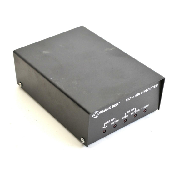
RS-232↔IEEE 488
Interface Converter
E R
P O W
R
E R R O
S R Q
N
L I S T E
T A L K
CUSTOMER
Order toll-free in the U.S. 24 hours, 7 A.M. Monday to midnight Friday: 877-877-BBOX
SUPPORT
FREE technical support, 24 hours a day, 7 days a week: Call 724-746-5500 or fax 724-746-0746
Mail order: Black Box Corporation, 1000 Park Drive, Lawrence, PA 15055-1018
INFORMATION
Web site: www.blackbox.com • E-mail: info@blackbox.com
Advertisement
Table of Contents

Related Manuals for Black Box RS-232 - IEEE 488 Interface Converter


Summary of Contents for Black Box RS-232 - IEEE 488 Interface Converter
- Page 1 Order toll-free in the U.S. 24 hours, 7 A.M. Monday to midnight Friday: 877-877-BBOX SUPPORT FREE technical support, 24 hours a day, 7 days a week: Call 724-746-5500 or fax 724-746-0746 Mail order: Black Box Corporation, 1000 Park Drive, Lawrence, PA 15055-1018 INFORMATION Web site: www.blackbox.com • E-mail: info@blackbox.com...
- Page 2 RS-232↔IEEE 488 INTERFACE CONVERTER EUROPEAN UNION DECLARATION OF CONFORMITY To maintain safety, emission, and immunity standards of this declaration, the following conditions must be met. • Serial and IEEE cables must have a braided shield connected circumferentially to their connectors’ metal shells. •...
- Page 3 WARNING! Noted conditions pertain to potential safety hazards. When you see a WARNING!, CAUTION!, or IMPORTANT! note, carefully read the information and be alert to the possibility of personal injury. Failure to follow these directives voids emission and immunity compliance. TRADEMARKS USED IN THIS MANUAL ®...
- Page 4 RS-232↔IEEE 488 INTERFACE CONVERTER FEDERAL COMMUNICATIONS COMMISSION INDUSTRY CANADA RADIO FREQUENCY INTERFERENCE STATEMENTS This equipment generates, uses, and can radiate radio frequency energy and if not installed and used properly, that is, in strict accordance with the manufacturer’s instructions, may cause interference to radio communication. It has been tested and found to comply with the limits for a Class A computing device in accordance with the specifications in Subpart J of Part 15 of FCC rules, which are designed to provide reasonable protection against such...
- Page 5 NOM STATEMENT NORMAS OFICIALES MEXICANAS (NOM) ELECTRICAL SAFETY STATEMENT INSTRUCCIONES DE SEGURIDAD 1. Todas las instrucciones de seguridad y operación deberán ser leídas antes de que el aparato eléctrico sea operado. 2. Las instrucciones de seguridad y operación deberán ser guardadas para referencia futura.
- Page 6 RS-232↔IEEE 488 INTERFACE CONVERTER 11. El aparato eléctrico deberá ser connectado a una fuente de poder sólo del tipo descrito en el instructivo de operación, o como se indique en el aparato. 12. Precaución debe ser tomada de tal manera que la tierra fisica y la polarización del equipo no sea eliminada.
-
Page 7: Table Of Contents
CONTENTS Contents Chapter Page 1. Specifications....................10 2. Introduction ....................12 2.1 Description ....................12 2.2 Abbreviations ..................13 3. Getting Started ....................14 3.1 Inspection ....................14 3.2 Configuration ..................14 3.3 Serial Port Settings ................16 3.3.1 Serial Baud Rate ................16 3.3.2 Serial Word Length (Data Bits) ..........18 3.3.3 Serial Stop Bits ................18 3.3.4 Serial Parity ................19 3.3.5 Serial Echo .................19... -
Page 8: Chapter Page
RS-232↔IEEE 488 INTERFACE CONVERTER Chapter Page 4.4 Talk-Back Features ................34 4.4.1 Talk-Back on Terminator............34 4.4.2 Talk-Back on Timeout...............36 4.5 Plotter Applications................38 4.6 Printer Applications ................44 5. Peripheral Operation..................45 5.1 Peripheral-Mode Operation ..............45 5.2 Serial and IEEE Input Buffers ..............45 5.3 IEEE Data Transfers ................46 5.3.1 Blind Bus Data Transfers............46 5.3.2 Controlled Bus Data Transfers ..........47 5.4 Serial-Poll Status-Byte Register .............48... - Page 9 CONTENTS Chapter Page 6.5 Handshake Lines...................57 6.5.1 Data Valid (DAV)...............57 6.5.2 Not Ready For Data (NRFD) ............57 6.5.3 Not Data Accepted (NDAC) .............57 6.6 Data Lines ....................58 6.7 Multiline Commands ................58 6.7.1 Go To Local (GTL) ..............58 6.7.2 Listen Address Group (LAG)............58 6.7.3 Unlisten (UNL) .................59 6.7.4 Talk Address Group (TAG) ............59 6.7.5 Untalk (UNT) ................59...
-
Page 10: Specifications
RS-232↔IEEE 488 INTERFACE CONVERTER 1. Specifications IEEE-488 Interface Implementation — C1, C2, C3, C4, and C28 controller subsets. Serial to IEEE: SH1, AH1, T6, TE0, L4, LE0, SR1, RL0, PP0, DC1, DT0, E1. Terminators — Selectable CR, LF, LF-CR, and CR-LF with EOI Connector —... - Page 11 CHAPTER 1: Specifications General Data Buffer — 32,000 characters dynamically allocated Indicators — LEDs for IEEE Talk and Listen, Serial Send and Receive, and Power Power — 105-125V or 210-250V; 50-60 Hz, 10 VA max. Size — 2.7"H x 5.5"W x 7.4"D (6.9 x 14 x 18.8 cm) Weight —...
-
Page 12: Introduction
RS-232↔IEEE 488 INTERFACE CONVERTER 2. Introduction 2.1 Description The RS-232↔488 Interface Converter provides transparent communication from a serial computer to an IEEE 488 printer, plotter, or other device. It also can be used to control a serial device, such as a printer or terminal, from an IEEE 488 host computer. -
Page 13: Abbreviations
CHAPTER 2: Introduction 2.2 Abbreviations The IEEE 488 abbreviations listed below are used throughout this manual. addr n IEEE bus address “n” Attention line Controller Active Controller Carriage Return data Data String Device Clear Group Execute Trigger Go To Local Listener Active Listen Address Group Line Feed... -
Page 14: Getting Started
RS-232↔IEEE 488 INTERFACE CONVERTER 3. Getting Started 3.1 Inspection The interface converter was carefully inspected, both mechanically and electrically, prior to shipment. When you receive it, carefully unpack all items from the shipping carton and check for any obvious signs of damage that may have occurred during shipment. - Page 15 CHAPTER 3: Getting Started 1 2 3 4 5 6 7 8 Switch Side View OPEN IEEE Addr IEEE Term Disabled 1 2 3 4 5 6 7 8 Switch Side View OPEN Mode Enabled Talk-Back on Timeout Serial Term No Echo Echo No Parity...
-
Page 16: Serial Port Settings
RS-232↔IEEE 488 INTERFACE CONVERTER Note that the interface converter comes configured as an IEEE controller. In this mode, the interface converter is designed to allow an RS-232 computer to communicate with an IEEE peripheral such as a plotter. This controller mode is described in detail in Chapter 4. - Page 17 CHAPTER 3: Getting Started 1 2 3 4 5 6 7 8 1 2 3 4 5 6 7 8 Switch 1800 Side View OPEN OPEN 1 2 3 4 5 6 7 8 1 2 3 4 5 6 7 8 2400 OPEN OPEN...
-
Page 18: Serial Word Length (Data Bits)
RS-232↔IEEE 488 INTERFACE CONVERTER 3.3.2 S ERIAL ENGTH SW1-6 determines the number of data bits, often referred to as word length, for each serial character transmitted or received. The factory default is 8 data bits. 1 2 3 4 5 6 7 8 1 2 3 4 5 6 7 8 Switch Side... -
Page 19: Serial Parity
CHAPTER 3: Getting Started 3.3.4 S ERIAL ARITY Serial Parity is selected with S2-6 through S2-8. The interface converter generates the selected parity during serial transmissions but it does not check parity on data that is received. The factory default is parity disabled. 1 2 3 4 5 6 7 8 1 2 3 4 5 6 7 8 Switch... -
Page 20: Serial Handshake
RS-232↔IEEE 488 INTERFACE CONVERTER 3.3.6 S ERIAL ANDSHAKE Switch SW1-5 is used to select hardware [RTS/CTS] or software [Xon/Xoff] serial handshake control. With X-ON/X-OFF, the interface converter issues an X-OFF character [ASCII value of $13] when its buffer memory is near full. When the X-OFF character is sent, there are still more than 1000 character locations remaining to protect against buffer overrun. -
Page 21: Selecting Terminator Substitution
CHAPTER 3: Getting Started 3.4 Selecting Terminator Substitution The interface converter can be configured to provide RS-232-to-IEEE-488 and IEEE-488-to-RS-232 terminator substitution. This is useful when interfacing an RS-232 device which only issues carriage return [CR] as an output terminator to an IEEE controller which expects a carriage return followed by a line feed [CR-LF]. -
Page 22: Ieee Bus Terminator
RS-232↔IEEE 488 INTERFACE CONVERTER 3.4.2 IEEE B ERMINATOR SW3-6 through SW3-8 set the IEEE bus terminators used for data sent or received by the interface converter. EOI, a line used to signal the end of a multiple character bus transfer, may also be enabled. If enabled, EOI is asserted when the last selected bus terminator is sent. -
Page 23: Selecting The Ieee Address
CHAPTER 3: Getting Started 1 2 3 4 5 6 7 8 1 2 3 4 5 6 7 8 Switch Side View OPEN OPEN Controller Mode Peripheral Mode Figure 3-10. Switch SW2: Selecting the Mode. 3.6 Selecting the IEEE Address SW3-1 through SW3-5 select the IEEE bus address of the interface converter when in the IEEE Peripheral mode. -
Page 24: Feature Selections
RS-232↔IEEE 488 INTERFACE CONVERTER 3.7 Feature Selections The functions of the remaining switches are dependent on the mode selected. A brief description of each of these features follows. You should refer to the listed sections for additional information. 3.7.1 C ONTROLLER EATURES In the IEEE Controller (RS-232-to-IEEE 488 Converter) mode, SW1-7 is... -
Page 25: Peripheral Features
CHAPTER 3: Getting Started 3.7.2 P ERIPHERAL EATURES In the IEEE Peripheral (IEEE 488 to RS-232 converter) mode, SW1-7 enables the interface to assert the SRQ IEEE bus interface line to indicate that it has received the last switch selected serial terminator character from the serial device. -
Page 26: Rs-232/Rs-422 Signal Level Selection
RS-232↔IEEE 488 INTERFACE CONVERTER 3.8.1 RS-232/RS-422 S IGNAL EVEL ELECTION The interface converter’s factory default signal levels are compatible with RS-232. To select RS-422 levels, carefully remove the 8-position shorting plug with a small flat blade screwdriver from J106. Install the DIP jumper into J205 making certain that all of the pins on the shorting plug are inserted correctly. - Page 27 CHAPTER 3: Getting Started Figure 3-16. Rear View of the Interface Converter’s Serial Connector. -RxD Receive Data—Input—Pin 2 This pin accepts serial data sent by the RS-232 or RS-422 host. The serial data is expected with the word length, baud rate, stop bits, and parity selected by the internal switches.
- Page 28 RS-232↔IEEE 488 INTERFACE CONVERTER Vtest Test Voltage—Output—Pin 6 This pin is connected to +5 volts through a 1K resistor. It is also common to Vtest on Pin 9. Ground—Pin 7 This pin sets the ground reference point for the other RS-232 inputs and outputs.
-
Page 29: Serial-Cable Wiring Diagrams
CHAPTER 3: Getting Started 3.8.3 S ERIAL ABLE IRING IAGRAMS If a cable was not purchased with the interface, the following diagrams will be helpful in making your own cable. Simple soldering skills and an attention to detail will ensure successful construction. Mini DINs Male DB25 Male RTS 1... -
Page 30: General Operation
RS-232↔IEEE 488 INTERFACE CONVERTER DB9 Female DB25 Male DCD 1 -RxD 2 3 -TxD -TxD 3 2 -RxD DTR 4 Gnd 5 7 Gnd DSR 6 RTS 7 4 CTS CTS 8 5 RTS Figure 3-19. Wiring Diagram: IBM AT or Compatible with DB9 Serial Connector to Interface Converter (RS-232). - Page 31 CHAPTER 3: Getting Started After plugging the power-supply connector into the interface, plug the power supply into AC line power. Turn the rear-panel power switch ON (the “1” position). All the front-panel indicators should light momentarily while the interface converter performs an internal ROM and RAM self-check. At the end of this self-check, all indicators except POWER should turn off.
-
Page 32: Controller Operation
RS-232↔IEEE 488 INTERFACE CONVERTER 4. Controller Operation 4.1 Controller-Mode (Serial to IEEE) Operation The IEEE Controller mode allows a serial RS-232 or RS-422 host device to send data to a single IEEE bus peripheral or to multiple peripherals if they occupy the same bus address. -
Page 33: Serial And Ieee Terminator Substitution
CHAPTER 4: Controller Operation 4.2 Serial and IEEE Terminator Substitution The interface converter can be configured to provide serial-to-IEEE-488 and IEEE-488-to-serial terminator substitution. This is useful when interfacing a serial host which only issues carriage return [CR] as an output terminator to an IEEE peripheral which expects a carriage return followed by a line feed [CR-LF]. -
Page 34: Ieee Address Selection
RS-232↔IEEE 488 INTERFACE CONVERTER 4.3 IEEE Address Selection SW3-1 through SW3-5 select the IEEE bus address of the IEEE peripheral the interface converter will be communicating with. These switches set the address of the IEEE device that will be controlled, not the address of the interface converter. - Page 35 CHAPTER 4: Controller Operation 1 2 3 4 5 6 7 8 1 2 3 4 5 6 7 8 Switch Side View OPEN OPEN Talk-Back on Talk-Back on Terminator Disabled Terminator Enabled Figure 4-2. Switch SW1: Enabling or Disabling “Talk-Back on Terminator.”...
-
Page 36: Talk-Back On Timeout
RS-232↔IEEE 488 INTERFACE CONVERTER 4.4.2 T ACK ON IMEOUT SW2-2 selects whether the interface converter should address the attached bus device to talk when the interface converter has no more serial data to send. This feature relies on time and not on terminators. Its use is primarily for simulating a serial plotter from an IEEE 488 (HP-IB) plotter. - Page 37 CHAPTER 4: Controller Operation The following is an example of how this feature can be used to communicate with an IEEE plotter. The program example is written in BASIC on an IBM PC or compatible. It turns the PC into a dumb serial terminal. When a key is pressed on the keyboard, the character is transmitted out of the serial (COM1) port.
-
Page 38: Plotter Applications
RS-232↔IEEE 488 INTERFACE CONVERTER 4.5 Plotter Applications To use the interface converter to interface an HP-IB plotter to a serial computer port, you will need the following information about your system: 1) The serial data format that the application (plotting or graphics) program expects the plotter to communicate with. - Page 39 CHAPTER 4: Controller Operation RS-232 IEEE 488 Interface Converter Figure 4-4. A PC-Based Graphics System. The following shows the interface converter’s internal switch settings required to use a Hewlett-Packard 7580A plotter with AutoCAD ® from AUTODESK on an IBM PC or compatible. Because PCs and compatibles output RS-232 levels, the shorting DIP jumper should be set to the RS-232 position (J206).
- Page 40 RS-232↔IEEE 488 INTERFACE CONVERTER 1 2 3 4 5 6 7 8 Switch Side View OPEN IEEE Addr CR Only IEEE Term Enabled 1 2 3 4 5 6 7 8 Switch Side View OPEN Mode Enabled Talk-Back on Timeout Serial Term No Echo Echo...
- Page 41 CHAPTER 4: Controller Operation File Edit Windows Settings for HP 7500A Baud Rate: 57600 Stop Bits: 1 Parity: Paper Si None Apple Plotter Graphic MP31 / 2 / 300 Houst Calcomp 104x/7x,9x5 H.P. 7220 Houst Calcomp 81 H.P. 7440A ColorPro Houst Colorwriter 6200DS10 H.P.
- Page 42 RS-232↔IEEE 488 INTERFACE CONVERTER Shorting Plug RS-422 RS-232 Figure 4-9. Setting the Internal DIP Shorting Jumper for RS-422. The following illustrates the interface converter’s internal switch settings for use with MacPlot, using the previously described format.
- Page 43 CHAPTER 4: Controller Operation 1 2 3 4 5 6 7 8 Switch Side View OPEN IEEE Addr IEEE Term Enabled 1 2 3 4 5 6 7 8 Switch Side View OPEN Mode Enabled Talk-Back on Timeout Serial Term No Echo Echo No Parity...
-
Page 44: Printer Applications
RS-232↔IEEE 488 INTERFACE CONVERTER 4.6 Printer Applications Most of the information given for plotter applications applies to applications for interfacing IEEE 488 printers to a serial host. Some high-end printers have a secondary command setting which must be disabled for the interface converter to control them. -
Page 45: Peripheral Operation
CHAPTER 5: Peripheral Operation 5. Peripheral Operation 5.1 Peripheral-Mode Operation This mode of operation is useful in interfacing a serial device, such as a serial printer, plotter or instrument, to an IEEE controller. Data which is sent by the IEEE controller to the interface converter is buffered and transmitted out its serial port. -
Page 46: Ieee Data Transfers
RS-232↔IEEE 488 INTERFACE CONVERTER When more than 10 queues become available, it asserts RTS or issues “X-ON.” The IEEE bus input signals that the IEEE input (or serial output) buffer is full when the number of queues available drops below 10 (1280 character locations left). -
Page 47: Controlled Bus Data Transfers
CHAPTER 5: Peripheral Operation 5.3.2 C ONTROLLED RANSFERS If the controller must avoid waiting for the serial device, it can “serial-poll” the interface converter. Serial polling is a method by which the controller can inquire the internal status of the interface without disturbing any data being transferred, slowing data transfers, or locking up the bus. -
Page 48: Serial-Poll Status-Byte Register
RS-232↔IEEE 488 INTERFACE CONVERTER 1 2 3 4 5 6 7 8 1 2 3 4 5 6 7 8 Switch Side View OPEN OPEN SRQ on Last SRQ on Last Terminator Enabled Terminator Disabled Figure 5-1. Switch SW1: Enabling or Disabling “SRQ on Last Terminator.”... - Page 49 CHAPTER 5: Peripheral Operation DIO7 serial-poll status information This bit is defined by the IEEE 488 Specification and is used to indicate to the bus controller that the interface converter is the bus device that requested service. It is cleared when the interface is serial polled by the controller.
-
Page 50: Use Of Serial And Bus Terminators
RS-232↔IEEE 488 INTERFACE CONVERTER 5.5 Use of Serial and Bus Terminators The interface converter can be configured to provide RS-232-to-IEEE-488 and IEEE-488-to-RS-232 terminator substitution. This is useful when interfacing a serial device that only issues carriage return [CR] as an output terminator to an IEEE controller that expects a carriage return followed by a line feed [CR-LF]. -
Page 51: My Talk Address (Mta)
CHAPTER 5: Peripheral Operation 5.6.1 M (MTA) DDRESS When the interface converter is addressed to talk, it retrieves data from the serial input buffer and outputs it to the IEEE 488 bus. It substitutes the selected IEEE bus terminators for the received serial terminators. The inter- face converter will continue to output serial input buffer data as long as the IEEE controller allows. -
Page 52: Ieee Address Selection
RS-232↔IEEE 488 INTERFACE CONVERTER 5.7 IEEE Address Selection SW3-1 through SW3-5 select the IEEE bus address of the interface converter when in the IEEE Peripheral mode. The address is selected by simple binary weighting with SW3-1 being the least significant bit and SW3-5 the most significant. -
Page 53: Ieee 488 Primer
CHAPTER 6: IEEE 488 Primer 6. IEEE 488 Primer 6.1 History The IEEE 488 bus is an instrumentation-communication bus adopted by the Institute of Electrical and Electronic Engineers in 1975 and revised in 1978. The interface converter conforms to this most recent revision, designated IEEE 488-1978. - Page 54 RS-232↔IEEE 488 INTERFACE CONVERTER At a committee meeting, everyone present usually listens. This is not the case with the GPIB. The Active Controller selects which devices will listen and commands all other devices to ignore what is being transmitted. A device is instructed to listen by being Addressed to Listen.
-
Page 55: Send It To My Address
CHAPTER 6: IEEE 488 Primer To Other Devices Device 1 System Controller Able to Talk, Listen, and Control Data Bus Device 2 Able to Talk Data Byte and Listen Transfer Control Device 3 Printer Only Able to Listen General Interface Management Device 4 Frequency Counter... -
Page 56: Bus Management Lines
RS-232↔IEEE 488 INTERFACE CONVERTER 6.4 Bus Management Lines Five hardware lines on the GPIB are used for bus management. Signals on these lines are often referred to as uniline (single line) commands. The signals are “active low”: A low voltage represents a logical “1” (asserted), and a high voltage represents a logical “0”... -
Page 57: Handshake Lines
CHAPTER 6: IEEE 488 Primer 6.5 Handshake Lines The GPIB uses three handshake lines in an “I’m ready—Here’s the data—I’ve got it” sequence. This handshake protocol assures reliable data transfer, at the rate determined by the slowest Listener. One line is controlled by the Talker, while the other two are shared by all Active Listeners. -
Page 58: Data Lines
RS-232↔IEEE 488 INTERFACE CONVERTER 1st Data Byte 2nd Data Byte DIO-8 (composite) Source Valid Valid Valid Valid None None NFRD Ready Ready Ready Ready Acceptor None None NDAC Accept Accept Accept Accept Acceptor Figure 6-2. IEEE Bus Handshaking. 6.6 Data Lines The GPIB provides eight data lines for a bit-parallel/byte-serial data transfer. -
Page 59: Unlisten (Unl)
CHAPTER 6: IEEE 488 Primer 6.7.3 U (UNL) NLISTEN This command tells all bus devices to Unlisten. The same as Unaddressed to Listen. ($3F) 6.7.4 T (TAG) DDRESS ROUP There are 31 (0 to 30) talk addresses associated with this group. The 3 most significant bits of the data bus are set to 010 while the 5 least significant bits are the address of the device being told to talk. -
Page 60: Take Control (Tct)
RS-232↔IEEE 488 INTERFACE CONVERTER 6.7.12 T (TCT) ONTROL This command passes bus control responsibilities from the current Controller to another device which has the ability to control. ($09 ) 6.7.13 S (SCG) ECONDARY OMMAND ROUP These are any one of the 32 possible commands (0 to 31) in this group. They must immediately follow a talk or listen address. -
Page 61: Serial Poll
CHAPTER 6: IEEE 488 Primer 6.8.1 S ERIAL Suppose the Controller receives a service request. For this example, let’s assume there are several devices which could assert SRQ. The Controller issues an SPE (Serial Poll enable) command to each device sequentially. If any device responds with DIO7 asserted, it indicates to the Controller that it was the device that asserted, SRQ. -
Page 62: Theory Of Operation And Board Layout
RS-232↔IEEE 488 INTERFACE CONVERTER 7. Theory of Operation and Board Layout 7.1 Theory of Operation The heart of the interface converter is a 6809 microprocessor (U101) supported by 8K bytes of firmware EPROM [U102 (2764)] and 32K bytes of static RAM [U103 (58256)]. A Versatile Interface Adapter [U104 (65B22)] is used to generate real-time interrupts for the firmware operating system. -
Page 63: Board Layout
CHAPTER 7: Theory of Operation and Board Layout 7.2 Board Layout J104 U110 U101 R102 C124 U107 U108 Figure 7-1. Component Layout of the Interface Converter’s Motherboard. - Page 64 RS-232↔IEEE 488 INTERFACE CONVERTER U201 P204 R205 R201 C201 U205 U206 R202 C202 C205 R203 C203 C209 C207 R207 C208 Figure 7-2. Component Layout of the Interface Converter’s Serial I/O board.
-
Page 65: Appendix A: Sample Dumb-Terminal Program
APPENDIX A: Sample Dumb-Terminal Program Appendix A. Sample Dumb-Terminal Program REM *** DUMB-TERMINAL PROGRAM FOR THE interface converter REM *** Running under IBM BASIC REM *** This Program allows direct interaction between the REM *** IBM PC and an IEEE bus device through the interface converter. -
Page 66: Appendix B: Character Codes And Ieee Multiline Messages
RS-232↔IEEE 488 INTERFACE CONVERTER Appendix B. Character Codes and IEEE Multiline Messages " & < > ACG = Addressed Command Group TAG = Talk Address Group UCG = Universal Command Group SCG = Secondary Command Group LAG = Listen Address Group... - Page 67 APPENDIX B: Character Codes and IEEE Multiline Messages How To Read the Chart Hexadecimal Decimal Equivalent Equivalent ASCII Character Address or Command...
-
Page 68: Index
RS-232↔IEEE 488 INTERFACE CONVERTER Index Abbreviations DIO4..........49 IEEE 488 .........13 DIO5..........49 Active Controller ......53 DIO6..........49 Address Selection DIO7..........49 IEEE ........34 DIO8..........48 Applications Echo..........19 Plotter ........38 End Or Identify ......56 Printer ........44 EOI 22, 56 ATN ..........56 Factory-Default Settings ..14, 15 Attention ........56 Feature Selections ......24 Baud Rate........16... - Page 69 INDEX Interface Clear ......51, 56 Package Contents ......14 Interface Converter Parallel Poll ........61 Connectors........26 Parallel Poll Configure....60 Introduction........12 Parallel Poll Unconfigure .....60 LAG ..........58 Peripheral Features .......25 LEDs ........31, 37, 43 Peripheral Mode......22, 23 Listen Address Group....58 Peripheral Operation ....45 Listen Only.......23, 52 Plotter Applications.......38 LLO ..........59...
- Page 70 RS-232↔IEEE 488 INTERFACE CONVERTER Serial Parity ........18 UNT..........51, 59 Serial Poll ........61 Untalk........51, 59 Serial Poll Disable....51, 59 Wiring Diagrams......29 Serial Poll Enable ....51, 59 IBM AT with DB9 Serial Port Settings ......16 Connector to Interface Serial Signal Descriptions .....26 Converter ........30 Serial Terminator ......21 IBM PC with DB25...
- Page 71 © Copyright 1998. Black Box Corporation. All rights reserved. 1000 Pasrk Drive • Lawrence, PA 15055-1018 • 724-746-5500 • Fax 724-746-0746...
Need help?
Do you have a question about the RS-232 - IEEE 488 Interface Converter and is the answer not in the manual?
Questions and answers