Table of Contents
Advertisement
Quick Links
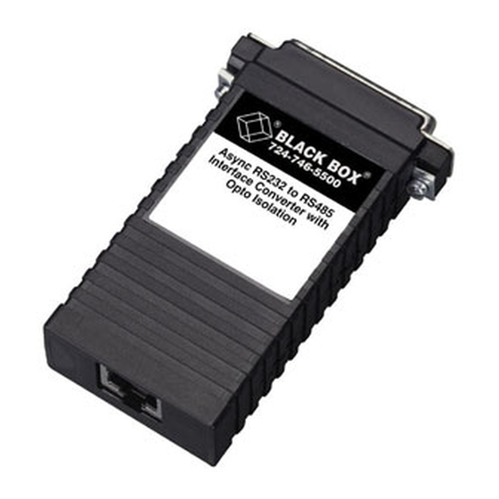
Async RS-232 to RS-485
Interface Converter
with Opto Isolation
CUSTOMER SUPPORT INFORMATION
Order toll-free in the U.S. 24 hours, 7 A.M. Monday to midnight Friday: 877-877-BBOX
FREE technical support, 24 hours a day, 7 days a week: Call 724-746-5500 or fax 724-746-0746
Mail order: Black Box Corporation, 1000 Park Drive, Lawrence, PA 15055-1018
Web site: www.blackbox.com • E-mail: info@blackbox.com
NOVEMBER 1999
IC525A-F
IC525A-M
IC526A-F
IC526A-M
IC525AE-F
IC525AE-M
IC526AE-F
IC526AE-M
Advertisement
Table of Contents

Related Manuals for Black Box IC525A-F


Summary of Contents for Black Box IC525A-F
- Page 1 Order toll-free in the U.S. 24 hours, 7 A.M. Monday to midnight Friday: 877-877-BBOX FREE technical support, 24 hours a day, 7 days a week: Call 724-746-5500 or fax 724-746-0746 Mail order: Black Box Corporation, 1000 Park Drive, Lawrence, PA 15055-1018 Web site: www.blackbox.com • E-mail: info@blackbox.com...
- Page 2 RS-232 TO RS-485 INTERFACE CONVERTER W/OPTO ISOLATION FEDERAL COMMUNICATIONS COMMISSION CANADIAN DEPARTMENT OF COMMUNICATIONS RADIO FREQUENCY INTERFERENCE STATEMENTS This equipment generates, uses, and can radiate radio frequency energy and if not installed and used properly, that is, in strict accordance with the manufacturer’s instructions, may cause interference to radio communication.
- Page 3 RS-232 TO RS-485 INTERFACE CONVERTER W/OPTO ISOLATION NORMAS OFICIALES MEXICANAS (NOM) ELECTRICAL SAFETY STATEMENT INSTRUCCIONES DE SEGURIDAD 1. Todas las instrucciones de seguridad y operación deberán ser leídas antes de que el aparato eléctrico sea operado. 2. Las instrucciones de seguridad y operación deberán ser guardadas para referencia futura.
- Page 4 NOM STATEMENT 10. El equipo eléctrico deber ser situado fuera del alcance de fuentes de calor como radiadores, registros de calor, estufas u otros aparatos (incluyendo amplificadores) que producen calor. 11. El aparato eléctrico deberá ser connectado a una fuente de poder sólo del tipo descrito en el instructivo de operación, o como se indique en el aparato.
- Page 5 RS-232 TO RS-485 INTERFACE CONVERTER W/OPTO ISOLATION TRADEMARKS The trademarks mentioned in this manual are the sole property of their owners.
-
Page 6: Table Of Contents
CONTENTS CONTENTS 1. Specifications ......6 2. Introduction......8 2.1 Description. -
Page 7: Specifications
Optical Isolation—2500 Vrms RS-232 Interface—DB25, female RS-422/485 Interface Options—RJ-45 or terminal block Connectors—IC525A-F: (1) DB25 female, (1) terminal block with strain relief; IC525A-M: (1) DB25 male, (1) terminal block with strain relief; IC526A-F: (1) DB25 female, (1) RJ-45; IC526A-M: (1) DB25 male, (1) RJ-45 Temperature—32 to 122 °F (0 to 50 °C) - Page 8 CHAPTER 1. Specifications Power—External power adapter, 5-VDC, 300 mA; “AE” models accept 220-volt input power Size—0.8"H x 2.1"W x 3.8"D (2 x 5.3 x 9.7 cm)
-
Page 9: Introduction
RS-232 TO RS-485 INTERFACE CONVERTER W/OPTO ISOLATION 2. Introduction 2.1 Description The Async RS-232 to RS-485 Interface Converter with Opto Isolation provides exceptional versatility in a compact package. The Converter comes with an external AC power adapter and supports asynchronous RS-232 data rates up to 115.2 kbps over one or two unconditioned twisted pairs. - Page 10 CHAPTER 2. Introduction • Up to 32 multipoint device drops in a polling environment. • Data rates to 115.2 kbps. • Passes transmit and receive data. • Operates via 5 V power supply. • Operates without “echo.” • Driver controlled as “constantly on,” “controlled by RTS,”...
-
Page 11: Configuration
RS-232 TO RS-485 INTERFACE CONVERTER W/OPTO ISOLATION 3. Configuration You can configure the Converter via a four-position DIP switch and two jumpers. Figure 3-1 shows the location of the DIP switch and the two headers on the board. DIP Switch 1 2 3 4 Power Figure 3-1. - Page 12 CHAPTER 3. Configuration Table 3-1. DIP Switch Default Settings. Position Function Switch Function RTS Control No RTS control of transmitter DTR Control No DTR control Reserved Transmitter Control ON Constantly ON Table 3-2. Switch Combinations (NOTE: JP4B is N/A). S1-1† S1-2†...
- Page 13 RS-232 TO RS-485 INTERFACE CONVERTER W/OPTO ISOLATION KEY TO TABLE 3-2 †S1-1, S1-2, and S1-4: only one switch can be ON at any time. The other two must be OFF. We recommend that you disconnect the Converter while changing configurations. *JP4A: If this jumper is off, only the RS-485 transmitter is controlled by RTS or DTR.
- Page 14 CHAPTER 3. Configuration S2: DTR C WITCH ONTROL When Switch S2 is in the ON position, the DTE input signal DTR (Pin 20) controls the transmitter of the Converter. In this mode, when DTR is high, the Converter transmits data from the RS-232 port to the RS-485 port.
-
Page 15: Jumpers
RS-232 TO RS-485 INTERFACE CONVERTER W/OPTO ISOLATION Setting Constant Transmitter Transmitter is controlled by RTS or DTR 3.2 Jumpers Jumper straps JP3 and JP4 control two-wire/four-wire and half-duplex/full-duplex operation, respectively. Table 3-3. Interface Card Strap Summary. Strap Function JP3A 2-wire/4-wire mode 2-wire 4-wire* JP3B 2-wire/4-wire mode 2-wire... -
Page 16: Installation
CHAPTER 4. Installation 4. Installation Once you have properly set the configuration switches and jumpers, you are ready to connect the Converter to your system. This section explains how to properly connect the Converter to the RS-485 and RS-232 interfaces, and how to operate the Converter. 4.1 Connection to the RS-485 Interface To function properly, the Converter must have one or two twisted pairs of metallic wire. - Page 17 RS-232 TO RS-485 INTERFACE CONVERTER W/OPTO ISOLATION Table 4-1. RJ-45 Signal/Pin Relationships. RJ-45 Signal 1 - - - - - - - - - - - - - - - - - - - - - - - - - - - - - N/C 2 - - - - - - - - - - - - - - - - - - - - - - - - - - - - - GND* 3 - - - - - - - - - - - - - - - - - - - - - - - - - - - - - RCV- 4 - - - - - - - - - - - - - - - - - - - - - - - - - - - - - XMT+...
-
Page 18: 2-Wire Connection Using Rj-45
SING ERMINAL LOCKS If you purchased the IC525A-F or IC525A-M, you will need to open the case to access the terminal blocks. The following instructions will tell you how to open the case, connect the bare wires to the terminal blocks, and fasten the strain-relief collar in place so that the wires won’t pull loose. - Page 19 RS-232 TO RS-485 INTERFACE CONVERTER W/OPTO ISOLATION Figure 4-3. Stripping the Outer Insulation from the Twisted Pairs. 3. Strip back the insulation on each of the 2 twisted pair wires about ⁄ inch as shown in Figure 4-4. Figure 4-4. Stripping the Insulation on the 2 Twisted Pairs. 4.
- Page 20 CHAPTER 4. Installation Figure 4-5. Completed Strain-Relief Assembly. 5. Connect the other pair of wires to RCV+ and RCV- (receive positive and negative) on both of the terminal blocks, again making careful note of which color is positive, and which is negative. Ultimately, you will want to construct a two-pair cross- over cable that makes a connection with the RS-422/485 device, as shown below.
-
Page 21: 2-Wire Connection Using Terminal
Most RS-485 devices employ a two-wire, half-duplex configuration. When using this configuration, be sure to first set the IC525A-F or IC525A-M to half-duplex mode by switching DIP switches and jumpers (refer to Chapter 3 for this configuration)—then use only the transmit (XMT) pair, as shown below. -
Page 22: Connection To The Rs-232 Interface
CHAPTER 4. Installation NOTE The ground connection is not needed. Host First Slave Other Slave(s) XMT+ - - - - - - - - - - - - - - - RCV+ - - - - - - - - - - - - - - - RCV+ XMT- - - - - - - - - - - - - - - - - RCV- - - - - - - - - - - - - - - - - RCV- RCV+ - - - - - - - - - - - - - - - XMT+ - - - - - - - - - - - - - - - XMT+ RCV- - - - - - - - - - - - - - - - - XMT- - - - - - - - - - - - - - - - - XMT-... -
Page 23: Operating The Converter
RS-232 TO RS-485 INTERFACE CONVERTER W/OPTO ISOLATION 4.4 Operating the Converter Once the Converter is properly installed, it should operate transparently—as if it were a standard cable connection. Operating power is derived from the RS-232 data and control signals; there is no “ON/OFF” switch. -
Page 24: Appendix: Rs-232 Pin Configurations
APPENDIX Appendix: Pin Configurations Direction “DCE Female” Setting Direction — —8 (DCD) Data Carrier Detect From Converter To Converter Data Terminal Ready (DTR) 20 —7 (SG) Signal Ground —6 (DSR) Data Set Ready —5 (CTS) Clear to Send —4 (RTS) Request to Send —3 (RD) Receive Data —2 (TD) Transmit Data —1 (FG) Frame Ground... - Page 25 RS-232 TO RS-485 INTERFACE CONVERTER W/OPTO ISOLATION RJ-45 Signal 1 - - - - - - - - - - - - - - - - - - - - - - - - - N/C 2 - - - - - - - - - - - - - - - - - - - - - - - - - GND* 3 - - - - - - - - - - - - - - - - - - - - - - - - - RCV- 4 - - - - - - - - - - - - - - - - - - - - - - - - - XMT+ 5 - - - - - - - - - - - - - - - - - - - - - - - - - XMT-...
- Page 26 © Copyright 1999. Black Box Corporation. All rights reserved. 1000 Park Drive • Lawrence, PA 15055-1018 • 724-746-5500 • Fax 724-746-0746...
Need help?
Do you have a question about the IC525A-F and is the answer not in the manual?
Questions and answers