Table of Contents
Advertisement
Quick Links
Non-Powered Interface Converters
CUSTOMER SUPPORT INFORMATION
Order toll-free in the U.S. 24 hours, 7 A.M. Monday to midnight Friday: 877-877-BBOX
FREE technical support, 24 hours a day, 7 days a week: Call 724-746-5500 or fax 724-746-0746
Mail order: Black Box Corporation, 1000 Park Drive, Lawrence, PA 15055-1018
Web site: www.blackbox.com • E-mail: info@blackbox.com
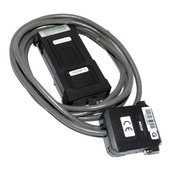
RS-232 to RS-530
RS-422 to V.35
RS-232 to RS-485
RS-232 to RS-422/RS-449
JUNE 1995
IC237A
IC486A
IC482A
IC487A-F
Advertisement
Table of Contents

Related Manuals for Black Box IC237A


Summary of Contents for Black Box IC237A
- Page 1 Order toll-free in the U.S. 24 hours, 7 A.M. Monday to midnight Friday: 877-877-BBOX FREE technical support, 24 hours a day, 7 days a week: Call 724-746-5500 or fax 724-746-0746 Mail order: Black Box Corporation, 1000 Park Drive, Lawrence, PA 15055-1018 Web site: www.blackbox.com • E-mail: info@blackbox.com...
-
Page 2: Table Of Contents
NON-POWERED INTERFACE CONVERTERS Contents Chapter Page 1. Specifications............1 1.1 IC237A.............1 1.2 IC482A.............2 1.3 IC486A.............4 1.4 IC487A-F............6 2. Introduction ............8 2.1 IC237A.............9 2.2 IC482A............10 2.3 IC486A............11 2.4 IC487A-F............13 3. Installation............14 3.1 IC237A............14 3.2 IC482A............18 3.3 IC486A............19 3.4 IC487A-F............24... -
Page 3: Specifications
NON-POWERED INTERFACE CONVERTERS 1. Specifications 1.1 IC237A Interface A — RS-232/V.24/V.28, DTE/DCE selectable Connectors — DB25 male Distance — Direct connection to RS-232/V.24 device Interface B — RS-530 (RS-422), DTE/DCE selectable DB25 female Connectors — Direct connection Distance — to RS-530 device... -
Page 4: Ic482A
NON-POWERED INTERFACE CONVERTERS Operating Temperature — 32° to 122°F (0° to 50°C) Humidity — Up to 90%, noncondensing Power — No AC power required Size — 0.9"H x 2.1"W x 4.3"D (2.3 x 5.3 x 10.9 cm) Weight — 14 oz. (397 g), including cable and connector 1.2 IC482A V.35, DTE only... - Page 5 NON-POWERED INTERFACE CONVERTERS Transmission Synchronous, transparent Format — to protocol Data Rates — Up to 2.048 Mbps Cable — 6.5 ft. (2 m) Input Voltage — Standard RS-422 and V.35 drivers Operating Temperature — 32° to 122°F (0° to 50°C) Up to 90%, noncondensing Humidity —...
-
Page 6: Ic486A
NON-POWERED INTERFACE CONVERTERS 1.3 IC486A Interface A — RS-232, DCE DB25F Connectors — Direct connection Distance — to RS-232 device Interface B — RS-422/485 (5) screw terminals Connectors — Distance — Up to 3.75 miles (6 km) Transmission Asynchronous only Format —... - Page 7 NON-POWERED INTERFACE CONVERTERS Data Carrier Detect (pin 8): Both are set by the DCD+DSR switch to be either high or open; Data Terminal Ready (pin 20): Should be connected for power considerations only, to constantly on (high). Carrier The Carrier is strap-selectable Control —...
-
Page 8: Ic487A-F
NON-POWERED INTERFACE CONVERTERS 0.9"H x 2.1"W x 4.3"D Size — (2.3 x 5.3 x 10.9 cm) Weight — 3 oz. (85 g) 1.4 IC487A-F Interface A — RS-232/V.24/V.28, DTE/DCE selectable DB25 male Connectors — Distance — Direct connection to RS-232/V.24 device Interface B —... - Page 9 NON-POWERED INTERFACE CONVERTERS 6.5 ft. (2 m) Cable — Input Voltage — Standard RS-232/V.24 driver ±12 volts Operating Temperature — 32° to 122°F (0° to 50°C) Humidity — Up to 90%, noncondensing Power — No AC power required Size — 0.9"H x 2.1"W x 4.3"D (2.3 x 5.3 x 10.9 cm) Weight —...
-
Page 10: Introduction
NON-POWERED INTERFACE CONVERTERS 2. Introduction The Non-Powered Interface Converters enable connection between DTE and DCE data- communi- cations equipment with different interfaces. The Converters perform both the physical and electrical conversion between the two interfaces. The circuitry is designed to provide short-range interface conversion. NOTE The devices that are to be connected must be within 6 feet (2 m) of each other. -
Page 11: Ic237A
Synchronous multiplexor terminal or multiplexor Fig. 2-1. X and Y interfaces are V.24 (RS-232) and RS-530. NOTE The DCE/DTE setting should be set to the type of unit to be connected to, not what the IC237A is to look like. -
Page 12: Ic482A
NON-POWERED INTERFACE CONVERTERS 2.2 IC482A RS-422 to V.35 (Model No. IC482A) is used for connecting a V.35 DCE device to an RS-422/449/ V.36 DTE device. RS-422 DTE V.35 DCE X Interface Y Interface Synchronous Synchronous modem or terminal or multiplexor multiplexor Fig. -
Page 13: Ic486A
NON-POWERED INTERFACE CONVERTERS 2.3 IC486A The RS-232 to RS-485 (Model No. IC486A) converts between RS-232/V.24 DTE devices and RS-485 equipment. It also enables multipoint connection of a computer and terminals in a mixed V.24 and RS-485 environment. (See Fig. 2-4.) This Converter’s carrier can be strapped to be constantly on or can be controlled by the Request to Send signal. - Page 14 NON-POWERED INTERFACE CONVERTERS RS-485 Host IC486A RS-485 RS-485 Printer Fig. 2-3. Interface converter, V.24/RS-232 to RS-485. IC486A IC486A IC486A RS-485 Fig. 2-4. Short-range modem in a multipoint environment.
-
Page 15: Ic487A-F
NON-POWERED INTERFACE CONVERTERS 2.4 IC487A-F RS-232 to RS-422/RS-449 (Model No. IC487A-F) is used to convert between V.24/RS-232 and V.36/ RS-422 interfaces. It’s switch-selectable either for connecting a V.24/RS-232 DTE to a V.36/RS-442 DCE, or for connecting a V.24 DCE to a V.36 DTE. Y Interface X Interface Synchronous... -
Page 16: Installation
NON-POWERED INTERFACE CONVERTERS 3. Installation 3.1 IC237A The Converter plugs directly into the DTE and the DCE. Connect the Converter directly to the RS-232/V.24 device, and the cable connector to the RS-530 device. The Converter comes factory-strapped for RS-232 DTE/RS-530 DCE, as shown in Figure 3-1. To change this configuration: 1. - Page 17 NON-POWERED INTERFACE CONVERTERS 4. Close the unit by pressing the two plastic covers together. (DTE) PORT (DCE) MODEM Fig. 3-1. RS-232 DTE, RS-530 DCE. (DTE) PORT (DCE) MODEM Fig. 3-2. RS-530 DTE, RS-232 DCE.
- Page 18 NON-POWERED INTERFACE CONVERTERS RS-530 (DTE) V.24 (DCE) Shield Proetctive Signal GND Signal GND RTS-a RTS-b CTS-a CTS-b DSR-a DSR-b DTR-a DTR-b LSD-a LSD-b TC-a TC-b RC-a RC-b EXT-TC-a EXT-TC EXT-TC-b TD a TD-b RC-a RC-b R = 100Ω Fig. 3-3. RS-530 DTE/RS-232 (V.24) DCE Schematic Diagram.
- Page 19 NON-POWERED INTERFACE CONVERTERS V.24 (DTE) RS-530 (DCE) Protective Shield Signal GND Signal GND RTS-a RS-b CTS-a CTS-b DSR-a DSR-b DTR-a DTR-b LSD-a LSD-b TC-a TC-b RC-a RC-b EXT-TC-a EXT-TC EXT-TC-b TD-a TD-b RD-a RD-b R = 100Ω Fig. 3-4. RS-232 (V.24) DTE/RS-530 DCE Schematic Diagram.
-
Page 20: Ic482A
NON-POWERED INTERFACE CONVERTERS 3.2 IC482A Installation is simple and straightforward. The Converter plugs directly into the DTE or DCE. No strapping adjustments are required. Connect the 37-pin connector to the RS-449/V.36 device and the other connector to the V.35 device, and it’s ready to operate. -
Page 21: Ic486A
NON-POWERED INTERFACE CONVERTERS 3.3 IC486A 1. Separate the two parts of the plastic cover by firmly pressing the marked places on the sides, starting at the cable end. Connect the RS-485 line to the Converter as follows: NOTE The A and B transmit and receive lines are as defined in RS-485. - Page 22 NON-POWERED INTERFACE CONVERTERS NOTE On the unit, up (≠) indicates ON and down (Ø) indicates OFF. 2. Set the internal switches according to Table 3-1. 3. Chassis GND: To connect the chassis ground (pin 1 or RS-232) to signal ground (pin 7 of RS-232), set chassis GND to CON.
- Page 23 NON-POWERED INTERFACE CONVERTERS 1 2 3 4 5 6 CHAS. GND Fig. 3-6. Strapping Diagram for the IC486A.
- Page 24 NON-POWERED INTERFACE CONVERTERS Table 3-1. Switch Selection Switch Function Possible Dfn. Factory Identity Positions Setting DCD+DSR (SW1) Both signals high. Both signals disconnected. CTS Status SW2 SW3 SW4 and RTS to CTS not provided. OFF OFF X CTS Delay CTS always high. OFF X (SW2, 3, 4) CTS follows RTS.
- Page 25 NON-POWERED INTERFACE CONVERTERS Table 3-2. Optional Connectors Signal Name RJ-11 Jack RJ-45 Jack Pin No. Color Pin No. Signal Ground 1, 6 Blue/Brown 1, 7 Transmit A Black Transmit B Yellow Receive A Receive B Green Table 3-3. Approximate Range (When Used as a Short-Range Modem) Data Rate 24 AWG (0.5 mm)
-
Page 26: Ic487A-F
NON-POWERED INTERFACE CONVERTERS 3.4 IC487A-F The Converter plugs directly into the DCE and the DTE. Connect the Converter directly to the RS-232/V.24 device, and the cable connector to the RS-449 device. The Converter comes factory- strapped for RS-232 DTE/RS-449 DCE, as shown in Figure 3-7. - Page 27 NON-POWERED INTERFACE CONVERTERS (DTE) PORT (DCE) MODEM Fig. 3-7. RS-232 DTE, RS-449 DCE (V.24 DTE, V.36 DCE). (DTE) PORT (DCE) MODEM Fig. 3-8. RS-449 DTE, RS-232 DCE (V.36 DTE, V.24 DCE).
- Page 28 NON-POWERED INTERFACE CONVERTERS V.36 (DTE) V.24 (DCE) Shield Frame GND 19,37,20 Signal GND Signal GND RS-a RS-b CS-a CS-b DM-a DM-b TR-a TR-b RR-a RR-b ST-a ST-b RT-a RT-b TT-a EXT-TC TT-b SD a SD-b RD-a RD-b R = 100Ω Fig.
- Page 29 NON-POWERED INTERFACE CONVERTERS V.24 (DTE) V.36 (DCE) Frame GND Shield 20,37,19 Signal GND Signal GND RS-a RS-b CS-a CS-b DM-a DM-b TR-a TR-b RR-a RR-b ST-a ST-b RT-a RT-b TT-a EXT-TC TT-b SD-a SD-b RD-a RD-b R = 100Ω Fig. 3-10. RS-232 (V.24) DTE/RS-449 (V.36) DCE Schematic Diagram (Factory Settings).
- Page 30 © Copyright 1995. Black Box Corporation. All rights reserved. 1000 Park Drive • Lawrence, PA 15055-1018 • 724-746-5500 • Fax 724-746-0746...
Need help?
Do you have a question about the IC237A and is the answer not in the manual?
Questions and answers