Table of Contents
Advertisement
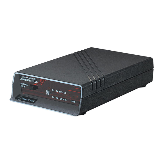
RS-232↔485/422 Converter Plus
RS-232↔485/422 Opto-Isolator/Converter
CUSTOMER
SUPPORT
INFORMATION
2 3 2 ↔ 4 8 5 /4 2 2
L U S
C O N V E R T E R P
N O R M A L
D L B
Order toll-free in the U.S.: Call 877-877-BBOX (outside U.S. call 724-746-5500)
FREE technical support 24 hours a day, 7 days a week: Call 724-746-5500 or fax 724-746-0746
Mailing address: Black Box Corporation, 1000 Park Drive, Lawrence, PA 15055-1018
Web site: www.blackbox.com • E-mail: info@blackbox.com
T S C D
R X T X R
D C E
D T E
C D
T X R X
2 3 2 ↔ 4 8 5 /4 2 2
O R /C O N V E R T
O P T O -I S O L A T
N O R M A L
D L B
IC108A
IC108C
IC108AE
P W R
R T S
E R
T S C D
R X T X R
D C E
D T E
R T S
C D
T X R X
APRIL 2002
IC109A
IC109A-R2
IC109C
IC109AE
P W R
Advertisement
Table of Contents

Related Manuals for Black Box IC108A


Summary of Contents for Black Box IC108A
- Page 1 Order toll-free in the U.S.: Call 877-877-BBOX (outside U.S. call 724-746-5500) SUPPORT FREE technical support 24 hours a day, 7 days a week: Call 724-746-5500 or fax 724-746-0746 INFORMATION Mailing address: Black Box Corporation, 1000 Park Drive, Lawrence, PA 15055-1018 Web site: www.blackbox.com • E-mail: info@blackbox.com...
-
Page 2: Specifications
FCC AND IC RFI STATEMENTS FEDERAL COMMUNICATIONS COMMISSION INDUSTRY CANADA RADIO FREQUENCY INTERFERENCE STATEMENTS This equipment generates, uses, and can radiate radio-frequency energy, and if not installed and used properly, that is, in strict accordance with the manufacturer’s instructions, may cause interference to radio communication. It has been tested and found to comply with the limits for a Class A computing device in accordance with the specifications in Subpart B of Part 15 of FCC rules, which are designed to provide reasonable protection against such interference when the equipment is... - Page 3 RS-232↔485/422 CONVERTERS NORMAS OFICIALES MEXICANAS (NOM) ELECTRICAL SAFETY STATEMENT INSTRUCCIONES DE SEGURIDAD 1. Todas las instrucciones de seguridad y operación deberán ser leídas antes de que el aparato eléctrico sea operado. 2. Las instrucciones de seguridad y operación deberán ser guardadas para referencia futura.
- Page 4 NOM STATEMENT 12. Precaución debe ser tomada de tal manera que la tierra fisica y la polarización del equipo no sea eliminada. 13. Los cables de la fuente de poder deben ser guiados de tal manera que no sean pisados ni pellizcados por objetos colocados sobre o contra ellos, poniendo particular atención a los contactos y receptáculos donde salen del aparato.
- Page 5 RS-232↔485/422 CONVERTERS TRADEMARKS USED IN THIS MANUAL Any trademarks mentioned in this manual are acknowledged to be the property of the trademark owners.
-
Page 6: Table Of Contents
CONTENTS Contents Chapter Page Specifications ..........6 Introduction . -
Page 7: Specifications
Humidity: 0 to 95% relative humidity, noncondensing MTBF: Approximately 180,000 hours (ground benign environment) Power: PS154 (for use with IC108A, IC109A): Input: 120 V, 60 Hz, 20W; Output: AC 17VCT, 0.7A; PS154E (for use with IC108AE, IC109AE): Input: 230 V, 50 Hz, 20W;... - Page 8 CHAPTER 1: Specifications Typical Speed Versus Distance (4-wire point-to-point 26-AWG twisted pair): Speed Distance 1200 bps 4 miles (6.4 km) 2400 bps 3 miles (4.8 km) 4800 bps 2.3 miles (3.7 km) 9600 bps 1.7 miles (2.7 km) 19,200 bps 1.2 miles (1.9 km) 38,400 bps 0.9 mile (1.4 km)
-
Page 9: Introduction
RS-232↔485/422 CONVERTERS 2. Introduction The RS-232↔485/422 Converter Plus is an RS-232-to-RS-485 interface converter that operates in the same manner as a line driver. It allows an RS-232 device to transmit data over much longer distances than is normally possible (up to 4 miles—6.4 km—at 1200 bps). -
Page 10: Installation
CHAPTER 3: Installation 3. Installation This section describes the jumper and switch functions for configuring the RS-232↔485/422 Converter. See Figure 1 on the next page for the component locations. To install your RS-232↔485/422 Converter: 1. Set each of the ten jumpers/switches for your application. 2. - Page 11 RS-232↔485/422 CONVERTERS NOTE When the jumper W9 (CTS) is in the ON position and jumper W15 is in the A-B position, the RS-485 driver is always turned on to enable transmission of data. Therefore, half-duplex transmission cannot be performed. See Section 3.1.5 for an explanation of the RS-485 driver. Figure 1.
-
Page 12: Cts Delay
CHAPTER 3: Installation 3.1.4 CTS D (W9 J ELAY UMPER When the transmitter of a device is first turned on, an unstable carrier signal is transmitted for several milliseconds. If data was sent during this period, it would be received as distorted information. Setting a CTS delay on the RS-232↔485/422 Converter allows the communications link to settle down before data can be sent. -
Page 13: Half-Duplex Turnaround Delay
RS-232↔485/422 CONVERTERS Driver Enabled by Data The RS-485 driver can also be enabled without requiring an RS-232 control lead to be asserted. When jumper W15 is placed in the B-C position, the driver is enabled when data is received on the RS-232 port of the RS-232↔485/422 Converter. As soon as the first bit of the first character is received at the RS-232 port, the RS-485 driver is enabled and an internal timer is started. -
Page 14: Normal/Loopback Operation
CHAPTER 3: Installation Point-to-Point When only two devices are connected to the line in a point-to-point application, each device should have the termination network connected to the line. Set switch S2 to the “TERM” position. Multipoint For multipoint applications, switch S2 should be in the “UNTERM” position on all the RS-232↔485/422 Converter devices in the network except for the two units at the extreme opposite locations on the line. -
Page 15: Dce Configuration/Dte Configuration
RS-232↔485/422 CONVERTERS 3.2 DCE/DTE Configuration This section contains block diagrams (Figures 2 and 4) and jumper and switch settings (Tables 1 and 2) for DCE/DTE operation. For a detailed description of the jumpers and switches, see Section 3.1. Figure 2. Simplified Functional Block Diagram (DCE Operation). - Page 16 CHAPTER 3: Installation Table 1. DCE Jumper Settings. NOTE For additional information on the jumper requirements, see Section 3.1. Function Jumper Requirements 1. Configure RS-232 port as DCE XW1 in A position 2. Signal ground connected to frame ground • Connected W7 is IN (solder your own 100-ohm, ⁄...
- Page 17 RS-232↔485/422 CONVERTERS Table 1 (continued). DCE Jumper Settings. Function Jumper Requirements 5. Enable RS-485 driver a. RS-485 driver enabled by RS-232 control leads • by RTS W15 in A-B position and W9 in 0-ms position W9 in 10-ms position W9 in 30-ms position b.
- Page 18 CHAPTER 3: Installation Table 1 (continued). DCE Jumper Settings. Function Jumper Requirements 7. RS-485 interface terminated or unterminated • Terminated S2 in TERM position • Unterminated S2 in UNTERM position 8. Normal or loopback operation • Normal mode S1 in Normal position •...
- Page 19 RS-232↔485/422 CONVERTERS Figure 3. Line Bias. S2 shows the line termination when “Term” is selected. S3 shows line bias when “Bias” is selected.
- Page 20 CHAPTER 3: Installation Opto-isolated barrier in IC109 models Figure 4. Simplified Functional Block Diagram (DTE Operation). NOTE The delay settings for W9 apply only to the CTS output of the RS-232↔ 485/422 Converter. Since CTS is not used when the RS-232↔485/422 Converter is configured as a DTE device, placing jumper W9 in either the 0-, 10-, or 30-msec position will allow the CD input to enable the RS-485 driver.
- Page 21 RS-232↔485/422 CONVERTERS Table 2. DTE Jumper Settings. NOTE For additional information on the jumper requirements, see Section 3.1. Function Jumper Requirements 1. Configure RS-232 port as DTE XW1 in B position 2. Signal ground connected to frame ground • Connected W7 is IN (100-ohm, 1/2-watt resistor soldered in place) •...
- Page 22 CHAPTER 3: Installation Table 2 (continued). DTE Jumper Settings. Function Jumper Requirements b. RS-485 driver enabled by data W15 in B-C position and • Disable timeout delay W17 msec 0.15 c. RS-485 driver constantly enabled W9 in ON position 6. Half-duplex turnaround delay W8 in HALF position and •...
-
Page 23: Typical Applications
RS-232↔485/422 CONVERTERS Table 2 (continued). DTE Jumper Settings. Function Jumper Requirements 9. RS-485 Interface Line Biased (Fail- S3 Off No line bias Safe), Receive S3 On Line biased NOTE If line bias is on, the RS-485 CD will ALWAYS be on. 3.3 Typical Applications This section describes some typical applications where the RS-232↔485/422 Converter might be used. - Page 24 CHAPTER 3: Installation Figure 5. Point-To-Point, 4-Wire (Full- or Half-Duplex). Figure 6. Point-to-Point, 2-Wire (Half-Duplex).
- Page 25 RS-232↔485/422 CONVERTERS Figure 7 shows a typical multipoint, 4-wire, full- or half-duplex connection. Figure 8 shows a typical multipoint, 2-wire, half-duplex connection. In the multipoint applications depicted in Figures 7 and 8, the devices at the extreme opposite ends of the installation are terminated by setting switch S2 to the TERM position. These devices are the two devices that have the greatest cable length between them, not necessarily the devices that are physically located the farthest apart.
- Page 26 CHAPTER 3: Installation Figure 8. Multipoint, 2-Wire (Half-Duplex). Sample 4-Wire Multipoint Configuration In the following application, an industrial controller is used to gather information from several remote programmable logic controller (PLC) stations (see Figure 9). A system protocol has been defined such that all the programmable logic controllers receive the information sent by the industrial controller, but only the remote station specifically addressed will respond.
- Page 27 RS-232↔485/422 CONVERTERS ↔ RS-232 485/422 Converter Plus Figure 9. Sample Multipoint Operation. Installation Procedure for the Multipoint Application in Figure 9 1. Set all the RS-232↔485/422 Converters for DCE operation (jumper XW1 in position A). 2. Connect a straight-through cable from the RS-232 port on each RS-232↔485/422 Converter to the RS-232 port on each of the PLCs.
- Page 28 CHAPTER 3: Installation 7. Since all the remote PLC stations must be inactive until addressed, the RS-485 driver of each remote RS-232↔485/422 Converter must not be constantly enabled (W9 of each remote RS-232↔485/422 Converter must be set to a position other than ON). The remote PLCs are fairly far from the industrial controller in our example, so it would be wise to set the CTS Delay (jumper W9) for 10 msec.
-
Page 29: Appendix A: Pinning
RS-232↔485/422 CONVERTERS Appendix A. Pinning Table 3. RS-232 interface (* denotes pins that are used). Circuit Description Signal Type Direction when configured as Protective Ground Ground Transmitted Data Data Input Output Receive Data Data Output Input Request to Send Control Input Output Clear to Send... - Page 30 APPENDIX A: Pinning Table 4. RS-485 pinning chart. Pin Name Description ↔ TXA and TXB Data received by the RS-232 485/422 Converter at the TXA=TX- RS-232 port is transmitted out of the unit over twisted- TXB=TX+ pair wires via these two outputs. The TX LED indicates the state of these two leads.
-
Page 31: Quick Reference: User-Selectable Options
RS-232↔485/422 CONVERTERS Quick Reference: User-Selectable Options Use this list as a quick-reference guide when you need to change the jumper settings. An asterisk (*) designates the factory-preset jumper settings. XW1A DCE* XW1B A-B* 4-wire 2-wire A-B* RTS/CD enabled Data enabled (Maximum speed is 64K.) A-B* RTS/CTS* delay (normal) RTS/CTS/CD delay (CTS inhibited if CD... - Page 32 QUICK REFERENCE: USER-SELECTABLE OPTIONS Turnaround delay (When W8 is in the B-C [2 wire] position, this is the time after the driver is disabled and before the receiver is enabled.) 0 msec 0.1 msec 1 msec 5 msec 35 msec NOTE If the Converter is configured Data Enabled (W15, position B-C) and 2- wire (W8 position B-C), then delays from W17 and W16 are cumulative.
- Page 33 © Copyright 2002. Black Box Corporation. All rights reserved. 1000 Park Drive • Lawrence, PA 15055-1018 • 724-746-5500 • Fax 724-746-0746...
Need help?
Do you have a question about the IC108A and is the answer not in the manual?
Questions and answers