Advertisement
Quick Links
CUSTOMER
Order toll-free in the U.S. 24 hours, 7 A.M. Monday to midnight Friday: 877-877-BBOX
FREE technical support, 24 hours a day, 7 days a week: Call 724-746-5500 or fax 724-746-0746
SUPPORT
Mail order: Black Box Corporation, 1000 Park Drive, Lawrence, PA 15055-1018
INFORMATION
Web site: www.blackbox.com • E-mail: info@blackbox.com
JUNE 2000
IC483A-R2
IC483AE-R2
IC483C-R2
Advertisement

Related Manuals for Black Box IC483AE-R2


Summary of Contents for Black Box IC483AE-R2
- Page 1 Order toll-free in the U.S. 24 hours, 7 A.M. Monday to midnight Friday: 877-877-BBOX FREE technical support, 24 hours a day, 7 days a week: Call 724-746-5500 or fax 724-746-0746 SUPPORT Mail order: Black Box Corporation, 1000 Park Drive, Lawrence, PA 15055-1018 INFORMATION Web site: www.blackbox.com • E-mail: info@blackbox.com...
- Page 2 FEDERAL COMMUNICATIONS COMMISSION CANADIAN DEPARTMENT OF COMMUNICATIONS RADIO FREQUENCY INTERFERENCE STATEMENTS This equipment generates, uses, and can radiate radio frequency energy and if not installed and used properly, that is, in strict accordance with the manufacturer’s instructions, may cause interference to radio communication.
- Page 3 13. Los cables de la fuente de poder deben ser guiados de tal manera que no sean pisados ni pellizcados por objetos colocados sobre o contra ellos, poniendo particular atención a los contactos y receptáculos donde salen del aparato. 14. El equipo eléctrico debe ser limpiado únicamente de acuerdo a las recomendaciones del fabricante. 15.
-
Page 4: Table Of Contents
CONTENTS 1. Specifications ..............4 2. -
Page 5: Specifications
Maximum Storage Temperature—158 °F (70 °C) Maximum Operating Temperature—122 °F (50 °C) Power—IC481A-R2, IC483A-R2: 115-VAC, 60-Hz, 16-watt power supply; IC483AE-R2: 230-VAC, 50-Hz, 16-watt power supply; IC481C-R2, IC483C-R2: Requires 16 watts from RM060 interface Size—Standalone: 2.3"H x 8"W x 11.9"D (5.8 x 20.3 x 30.2 cm);... -
Page 6: Introduction
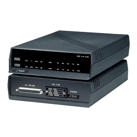
2. Introduction The V.35 ↔ RS-422 Interface Converter comes in both 115-VAC (IC483A-R2) and 230-VAC (IC483AE-R2) standalone units. A card version (IC483C-R2) is available for rack-mounting. The rack (RM060) is switch- selectable for either 115-VAC or 230-VAC operation. The V.35 ↔ RS-422 Interface Converter provides bidirectional conversion of all the commonly used V.35 and RS-422 signals. -
Page 7: Installation
3. Installation 3.1 DIP Shunt Settings V.35 ↔ RS-422 Interface Converter has two jumper-selectable configurations determined by DIP shunt settings located inside the unit on the printed circuit board. One configuration is for connecting a V.35 DCE device to a 422 DTE device, and the other is for connecting a V.35 DTE to a 422 DCE device. - Page 8 To install the V.35 ↔ RS-422 Interface Converter, follow these steps and refer to Figures 3-1 and 3-2. 1. Set jumper XW6 to the V.35 side when configuring the V.35 side of the unit as DTE. Set XW6 to the 422 side when configuring the RS-422 side of the unit as DTE.
- Page 9 DTE DCE V.35 DTE RS-422 DTE Figure 3-2. Board Layout Showing LED Indicators and Plug Connectors.
-
Page 10: Leds
3.2 LEDs The V.35 ↔ RS-422 Interface Converter has ten LED indicators on its front panel. The row of type above the LEDs indicates the uses of the LEDs for an RS-422 DTE/V.35 DCE configuration. The row of type below the LEDs indicates the uses of the LEDs for a V.35 DTE/RS-422 DCE configuration. -
Page 11: Ground Strap And Pin Connections
4. Ground Strap and Pin Connections 4.1 Ground Strap Signal grounds (pins 19, 20, and 37 on the 422 interface and pin B on the V.35 interface) are connected together, but not connected to chassis ground (pin A). To connect signal ground to frame ground, install a 100-ohm, ⁄... -
Page 12: Pin Connections
4.2 Pin Connections Figures 4-1 and 4-2 show the pin connections for the V.35 ↔ RS-422 Interface Converter. The pins that are grayed out in these figures indicate signals tied to the front-panel LEDs only. The Converter is shipped with the RS-422 port configured as DCE and the V.35 port configured as DTE. 1 In this configuration, pins 12 and 30 are inputs. - Page 13 The Converter is shipped with the Terminal Ready jumper in the True (ON) position. DTR/DM DS10 POWER Figure 4-5. The Converter Configured for RS-422 as DTE and V.35 as DCE.
- Page 14 DM/DTR DS10 POWER Figure 4-6. The Converter Configured for RS-422 as DCE and V.35 as DTE.
- Page 15 © Copyright 2000. Black Box Corporation. All rights reserved. 1000 Park Drive • Lawrence, PA 15055-1018 • 724-746-5500 • Fax 724-746-0746...
Need help?
Do you have a question about the IC483AE-R2 and is the answer not in the manual?
Questions and answers