
Related Manuals for Black Box IC124A


Summary of Contents for Black Box IC124A
- Page 1 © Copyright 2000. Black Box Corporation. All rights reserved. 1000 Park Drive • Lawrence, PA 15055-1018 • 724-746-5500 • Fax 724-746-0746...
- Page 2 Order toll-free in the U.S. 24 hours, 7 A.M. Monday to midnight Friday: 877-877-BBOX SUPPORT FREE technical support, 24 hours a day, 7 days a week: Call 724-746-5500 or fax 724-746-0746 INFORMATION Mail order: Black Box Corporation, 1000 Park Drive, Lawrence, PA 15055-1018 Web site: www.blackbox.com • E-mail: info@blackbox.com...
- Page 4 FCC AND DOC/MDC STATEMENTS FEDERAL COMMUNICATIONS COMMISSION INDUSTRY CANADA RADIO FREQUENCY INTERFERENCE STATEMENTS This equipment generates, uses, and can radiate radio frequency energy and if not installed and used properly, that is, in strict accordance with the manufacturer’s instructions, may cause interference to radio communication. It has been tested and found to comply with the limits for a Class A computing device in accordance with the specifications in Subpart J of Part 15 of FCC rules, which are designed to provide reasonable protection against such interference when the equipment is...
- Page 5 SCSI DIFFERENTIAL CONVERTERS NORMAS OFICIALES MEXICANAS (NOM) ELECTRICAL SAFETY STATEMENT INSTRUCCIONES DE SEGURIDAD 1. Todas las instrucciones de seguridad y operación deberán ser leídas antes de que el aparato eléctrico sea operado. 2. Las instrucciones de seguridad y operación deberán ser guardadas para referencia futura.
- Page 6 NOM STATEMENT 12. Precaución debe ser tomada de tal manera que la tierra fisica y la polarización del equipo no sea eliminada. 13. Los cables de la fuente de poder deben ser guiados de tal manera que no sean pisados ni pellizcados por objetos colocados sobre o contra ellos, poniendo particular atención a los contactos y receptáculos donde salen del aparato.
- Page 7 SCSI DIFFERENTIAL CONVERTERS TRADEMARKS USED IN THIS MANUAL Centronics is a registered trademark of Centronics Corporation. Any other trademarks mentioned in this manual are acknowledged to be the property of the trademark owners.
-
Page 8: Table Of Contents
5.1 Contacting Black Box ........ -
Page 9: Chapter Page
SCSI DIFFERENTIAL CONVERTERS Chapter Page C.6 Removing or Replacing Fuses ......33 C.7 Closing the Converter . -
Page 10: Specifications
Interfaces — IC124A: Narrow SCSI; IC125A: SE to HVD Wide SCSI; IC152A: SE/LVD to HVD Wide SCSI Compatibility — IC124A: SCSI-1 and Fast SCSI (SCSI-2); IC125A: Fast SCSI (SCSI-2); IC152A: SCSI-1, SCSI-2, SCSI-3, and Ultra-SCSI-2 Protocol — Synchronous or asynchronous Maximum Data Rate —... - Page 11 Indicator — (2) Front-mounted LEDs: Power, Bus Active Connectors — All rear-mounted: (1) IEC 320 male power inlet; IC124A only: (1) 50-pin Centronics female for single-ended SCSI data; (1) 50-pin high-density female for differential SCSI data; IC125A only: (2) 68-pin high-density female for single-ended...
- Page 12 CHAPTER 1: Specifications Power — Through detachable power cord and internal power supply: Optimal Input: 110 VAC, 60 Hz, or 220 VAC, 50 Hz (user-selectable); Input Range: 99 to 121 VAC or 198 to 242 VAC, 48 to 65 Hz; Input Current Rating: 1.5 amps;...
-
Page 13: Introduction
The “narrow SCSI” Converter (product code IC124A) is fully compatible with 8-bit SCSI-1 and Fast SCSI (SCSI-2) applications; the “wide SCSI” Converters (product code IC125A and IC152A) are fully compatible with 16-bit Fast SCSI applications. -
Page 14: Hardware Description
The IC152A is also a 25-meter extender. The Converters support a maximum SCSI data rate of 10 MBps (IC124A), 20 MBps (IC125A), or 80 MBps (IC152A) in asynchronous or synchronous mode. All models support the “Fast SCSI” standard available in top-of-the-line computers and peripherals. - Page 15 SCSI DIFFERENTIAL CONVERTERS Single-ended SCSI Differential SCSI chain, up to 6 m chain, up to 25 m (19.7 ft.) long (82 ft.) long Differential peripherals Converter Computer w/single- ended host adapter Differential SCSI chain, up to 25 m (82 ft.) long Converter Converter Computer...
-
Page 16: Installation
Customers in North America and certain other world regions will also receive an AC power cord. If you didn’t receive everything, or if anything arrived damaged, call Black Box immediately. 3.2 Configuration You will have to open the SCSI Differential Converter and make adjustments to its internal components if you need to do any of these things: •... -
Page 17: Placement
SINGLE-ENDED PORT DIFFERENTIAL PORT Figure 3-1. The rear panel of the SCSI Differential Converter (the narrow model, IC124A, shown). 3.4.2 P OWERING OWN THE YSTEM... - Page 18 CHAPTER 3: Installation 3.4.3 C SCSI B ONNECTING THE ONVERTER TO THE Install the SCSI Differential Converter at one end or the other of the single-ended SCSI chain and differential chain that you want to interconnect. (That is, run standard single-ended cable to the Converter from either the first or last device on the single-ended chain, and run standard differential cable to the Converter from either the first or last device on the differential chain.) The Converter has one single-ended (50-pin Centronics...
- Page 19 SCSI DIFFERENTIAL CONVERTERS Computer Peripherals Converter T = required terminators that you must have present T* = required terminators that are already there (internal to the Converter) Figure 3-1. Termination in a SCSI Differential Converter system. Your SCSI Differential Converter comes standard with internal terminators that provide the necessary termination on each side of the Converter.
-
Page 20: Operation
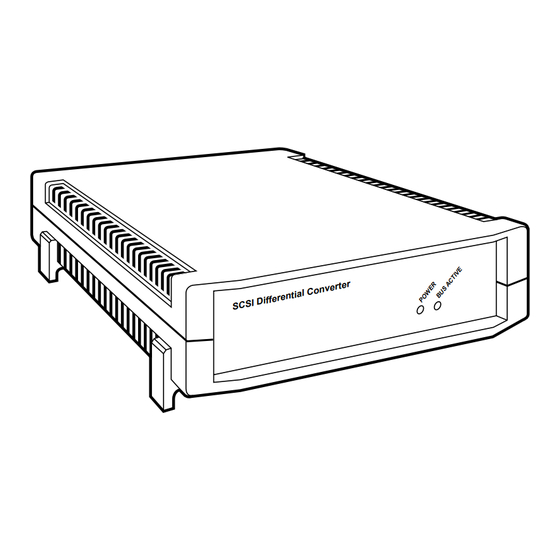
CHAPTER 4: Operation 4. Operation 4.1 The Front Panel and Its LEDs Each SCSI Differential Converter has two LEDs on its front panel, shown in Figure 4-1 below, that give you at-a-glance status information about the unit’s operation: Power—Lights when the unit is plugged in, turned ON, and receiving AC power. Bus Active—Dark when there is no communication on the SCSI bus;... - Page 21 SCSI DIFFERENTIAL CONVERTERS reduce the data-transfer rates between certain peripheral devices and host adapters, and it increases the time required for Arbitration, Selection, and Reselection.
-
Page 22: Troubleshooting
• If you are shipping the Converter for repair, make sure you include its power cord and its bag of replacement parts. If you are returning the Converter, make sure you include everything you received with it. Before you ship, contact Black Box to get a Return Materials Authorization (RMA) number. -
Page 23: Appendix A: Connector Pinouts
Appendix A: Connector Pinouts A.1 Single-Ended Narrow SCSI (50-Pin Centronics) Port (IC124A) The single-ended narrow SCSI port on the IC124A model of the SCSI Differential Converter are pinned as shown in Table A-1 below. Table A-1. Pinout Chart for Single-Ended Narrow SCSI Connectors... -
Page 24: Differential Narrow Scsi (50-Pin High-Density) Ports (Ic124A)
APPENDIX A: Connector Pinouts A.2 Differential Narrow SCSI (50-Pin High-Density) Port (IC124A) The differential narrow SCSI ports on the IC124A model of the SCSI Differential Converter are pinned as shown in Table A-2 below. Table A-2. Pinout Chart for Differential Narrow SCSI Connectors... -
Page 25: Single-Ended Wide Scsi (68-Pin High-Density) Ports (Ic125A)
SCSI DIFFERENTIAL CONVERTERS A.3 Low-Voltage Differential (LVD) 16-Bit SCSI Wide (IC152A Models) The IC125A’s single-ended wide SCSI ports are pinned as shown in Table A-3 below. Table A-3. Pinout Chart for Low-Voltage Differential (LVD) SCSI Connectors Signal Name Pin Number Signal Name Pin Number +DB(12) -
Page 26: Differential Wide Scsi (68-Pin High-Density) Ports (Ic125A)
APPENDIX A: Connector Pinouts Table A-3 (continued). Pinout Chart for Low-Voltage Differential (LVD) SCSI Connectors Signal Name Pin Number Signal Name Pin Number +I/O -I/O +DB(8) -DB(8) +DB(9) -DB(9) +DB(10) -DB(10) +DB(11) -DB(11) A.4 Differential Wide SCSI (68-Pin High-Density) Ports (IC125A) The IC125A’s differential wide SCSI ports are pinned as shown in Table A-4 below. - Page 27 SCSI DIFFERENTIAL CONVERTERS Table A-4 (continued). Pinout Chart for Differential Wide SCSI Connectors Signal Name Pin Number Signal Name Pin Number GROUND GROUND –BSY +BSY –ACK +ACK –RST +RST –MSG +MSG –SEL +SEL –C/D +C/D –REQ +REQ –I/O +I/O GROUND GROUND –DB(8) +DB(8)
-
Page 28: Appendix B: Scsi Technical Information
APPENDIX B: SCSI Technical Information Appendix B: SCSI Technical Information B.1 SCSI Basics This section briefly discusses some of the major topics involved with the SCSI (Small Computer Systems Interface). SCSI-1 The original specification supported data transfers up to 5 MBps on an 8-bit-wide parallel data bus. -
Page 29: Scsi Installation Tips
SCSI DIFFERENTIAL CONVERTERS Differential wiring uses two wires for each signal and offers exceptional noise resistance because it does not rely on a common ground. This allows cables up to 25 meters and reliable operation at 10 MBps or greater. Differential wiring and circuitry is more complex than single-ended and generally tends to be more expensive to implement. -
Page 30: Scsi Signal Descriptions
APPENDIX B: SCSI Technical Information Know that some SCSI-ID numbers may be reassigned. Internal boot-source hard drives are usually set to ID “0,” while secondary hard drives are set to “1.” Motherboards and host adapters are generally set to ID “7.” Always terminate the first and last devices on the chain. - Page 31 SCSI DIFFERENTIAL CONVERTERS ACK (ACKNOWLEDGE): A signal driven by an initiator to indicate an acknowledgement for a REQ/ACK data-transfer handshake. ATN (ATTENTION): A signal driven by an initiator to indicate the ATTENTION condition. RST (RESET): A signal that indicates the RESET condition. DB(15 or 7 through 0, plus P) (DATA BUS): Sixteen (for Wide SCSI) or eight (for Narrow SCSI) data-bit signals, plus a parity-bit signal, that form a DATA BUS.
-
Page 32: Appendix C: Internal Adjustments
APPENDIX C: Internal Adjustments Appendix C. Internal Adjustments Certain procedures for configuring or reconfiguring the SCSI Differential Converter—specifically, those listed in Section 3.2 of the manual text and described in Sections C.2 through C.6 of this appendix—require you to open the unit’s chassis and set, remove, or replace some of its internal components. - Page 33 SCSI DIFFERENTIAL CONVERTERS MODEL NO: ACI– 1080 SERIAL NO: 300100 INPUT VOLTAGE 115 VAC Figure C-1. Locations of the screws that must be removed.
- Page 34 APPENDIX C: Internal Adjustments 1.5A @ 250V Figure C-2. The circuit board of a “narrow” Converter (IC124A).
-
Page 35: Setting The Converter For 220-Vac Input Power
W5. C.5 Replacing Internal Terminators If a surge or other electrical problem damages any of the SCSI Differential Converter’s internal terminators, you might need to replace them; call Black Box Technical Support for replacements. - Page 36 Converter and some soldering, and should only be attempted by a trained professional; call Black Box for technical support. If you need to replace either of these parts for a second or subsequent time, call Black Box for technical support.
Need help?
Do you have a question about the IC124A and is the answer not in the manual?
Questions and answers