Table of Contents

Related Manuals for Ancona Elite


Summary of Contents for Ancona Elite
- Page 1 Ancona Elite Gas Cooktop 36" User Manual & Installation Instructions IMPORTANT SAFETY INSTRUCTIONS Carefully read the important information regarding installation, safety and maintenance. Keep these instructions for future reference.
-
Page 2: Important - Please Read And Follow
BUILT-IN GAS COOKTOP • USERS OPERATING INSTRUCTIONS • INSTALLATION ADVICE IMPORTANT - PLEASE READ AND FOLLOW √ Before beginning please read these instructions completely and carefully. √ Do not remove permanently affixed labels, warnings, or plates from the product. This may void the warranty. - Page 3 Dear Customer, Thank you for having purchased and given your preference to our product. The safety precautions and recommendations reported below are for your own safety and that of others. They will also provide a means by which to make full use of the features offered by your appliance.
-
Page 4: User Instruction
USER INSTRUCTION IMPORTANT PRECAUTIONS AND RECOMMENDATIONS • After having unpacked the appliance, check to ensure that it is not damaged. If you have any doubts, do not use it and consult your supplier or a professionally qualified technician. • Packing elements (i.e. plastic bags, polystyrene foam, nails, packing straps, etc.) should not be left around within easy reach of children, as these may cause serious injuries. -
Page 5: Control Panel Description
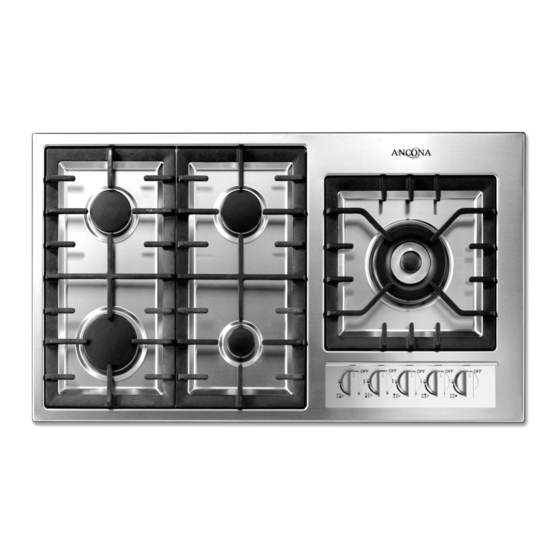
FEATURES Fig. 1.1 COOKING POINTS 1. Auxiliary burner (A) - 3500 BTU/hr 2. Rapid burner (R) - 10500 BTU/hr 3.Semi rapid burner (SR) - 6000 BTU/hr 4.Triple flame burner (TC) - 15000 BTU/hr CONTROL PANEL DESCRIPTION 5.Auxiliary burner (A) control knob (1) 6.Rapid burner (R) control knob (2) 7.Semi rapid burner (SR) control knob (3) 8.Semi rapid burner (SR) control knob (3) -
Page 6: Using The Gas Cooktop
USING THE GAS COOKTOP GAS BURNERS Gas flow to the burners is adjusted by turning the knobs (illustrated in fig. 2.1) which control the valves. Turning the knob so that the indicator line points to the symbols printed on the panel achieves the following functions: = closed valve = maximum rate... -
Page 7: Cleaning And Maintenance
CLEANING AND MAINTENANCE GENERAL RECOMANDATION √ Before you begin cleaning you must ensure that the hob is switched off. Do not use steam jet cleaners It is advisable to clean when the appliance is cold. because the humidity could √ All enamelled surfaces have to be washed with soapy water or some infiltrate into the appliance other non-abrasive product with a sponge and are to be dried preferably... - Page 8 CORRECT REPLACEMENT OF THE BURNERS it is very important to check that the burner flame spreader “F” and the cap “C” have been correctly positioned (see figs. 3.1 and 3.2). Failure to do so can cause serious problems. In appliances with electric ignition check that the electrode “S”...
-
Page 9: Installation Instructions
INSTALLATION INSTRUCTIONS WARNING! THIS APPLIANCE HAS TO BE INSTALLED BY A QUALIFIED INSTALLER. Improper installation, adjustment, alteration, services, or maintenance can cause injury or property damage. Consult a qualified installer, service agent, or the gas supplier. Screwdriver Wrench Tape measure T-handle wrench Angle hexagon key Pencil... -
Page 10: General Information
GENERAL INFORMATION WARNING!! 1. Installation must conform with local codes or, in the ELECTRICAL GROUNDING INSTRUCTIONS absence of local codes, with the National Fuel Gas Code, ANSI Z223.1 -Latest Edition. The cooktop must be electrically grounded in accor- dance with local codes or, in the absence of local codes, 2. - Page 11 INSTALLATION TO THE CABINET...
-
Page 12: Proximity To Side Cabinets
PROXIMITY TO SIDE CABINETS Important: Base cabinet construction must allow for size of cooktop cut-out. Gas line opening: Wall - anywhere 11” 51/64 (300 mm) below underside of countertop; Cabinet floor - anywhere 3” 1/8 (79.2 mm) from the rear wall. Grounded outlet: the electric cord with 3-pronq ground plug has a length of 48”... -
Page 13: Gas Connections
GAS CONNECTIONS All gas connections must be made according to nati6nal and local co- WARNING des. This gas supply (service) line must be the same size or greatest than the inlet line of the appliance. Sealant on all pipe joints must be resistant to the action of LP/Propane gas. - Page 14 GAS CONNECTION SPECIFICATION fig.5.2...
- Page 15 b) Any conversion required must be performed by your dealer or a qualified Iicensed plumber or gas service company. Please provide the service person with this manual before work is started on the cooktop. (Gas conversions are the responsibility of the dealer or end user.) c) This cooktop can be used with NATURAL or LP/PROPANE gas.
-
Page 16: Conversion To Lp/Propane Gas
CONVERSION TO LP/PROPANE GAS Every cooktop is provided with a set of injectors for the various types of gas. Select the injectors to be replaced according to the table below. The nozzle diameters, expressed in hundredths of a millimetre, are marked on the body of each injectors. SETTING THE PRESSURE REGULATOR (Fig. -
Page 17: Injectors Table
OPERATIONS TO BE PERFORMED WHEN SUBSTITUTING THE INJECTORS • Remove the gratings, the burner covers and the knobs; • Using a wrench substitute the nozzle injectors “J” (fig: 5.4 - 5.5) with those most suitable for the kind of gas for which it is to be used. -
Page 18: Electrical Connection
ELECTRICAL CONNECTION If codes permit and a separate ground wire is used, it is recom- WARNING mended that a qualified electrician determine that the ground path IS adequate. Check with a qualified electrician if you are not sure whether the cooktop is properly grounded. Do Not ground to a gas pipe. - Page 19 WIRING DIAGRAM IGNITION AS fig. 6.2 1 - Terminal block 2 - Ignition switches group 3 - Ignition generation 4 - Igniter 5 - Ignition and reigniter generation 6 - Ignition swithes fig. 6.3 WIRING DIAGRAM IGNITION AND REIGNITER...
- Page 20 Ancona is in association with Mr Appliance for all after sales service calls. Please contact their service provider or visit their website: Phone: 888-998-2011 Website: www.mrappliance.com MAAN2136-01 © 2015 Copyright of Ancona Home. All rights reserved. This material may not be reproduced, displayed, modified or distributed. — 16 —...
Need help?
Do you have a question about the Elite and is the answer not in the manual?
Questions and answers