Advertisement
Quick Links
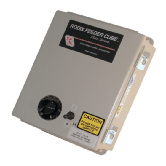
RODIX INC.
FEEDER CUBE
Plus Series
CE-40
Plus
CE-41
P/N 121-500-0746
PRODUCT DESCRIPTION
This device, P/N 121-500-0746, is used to control
the vibration level a vibratory feeder. The unit is
powered from the incoming line connection. The
unit has its own Master Control PC board. The
setup and operation is detailed in the following
product literature.
SPECIFICATIONS
Line Voltage:
Line Frequency:
Current:
Output Voltage:
Handling & Transp. Temp.
Operating Temp.
INSTALLATION
The control is to be firmly mounted to a non-
vibrating surface.
The control is designed to
withstand conditions equal to IP54. Do not install
the control in a more severe environment.
Connections to external conduits or cords are to
be made with hardware that is rated at IP54 or
better.
Refer to the electrical wiring diagram. Line and
load wiring is to be brought into the box via
customer-drilled holes. Use 2.5mm
Mains supply wires or larger.
(#14AWG) load wires or larger. The Mains supply
wires should be fused by the Customer at 15 amps
or less. After the wiring has been completed,
verify the continuity of the ground bond connection
to the control.
This control is for industrial use. Use in residential
areas may cause interference, and in that case,
special measures may have to be taken by the
user regarding emissions.
IMPORTANT - The vibratory feeder must be
tuned to match the power line frequency of the
destination country (50 or 60 Hz). A feeder
tuned to the wrong frequency will not feed
parts. The Rodix control operates on 50 or 60
Hz.
When installing this control, a power supply
disconnect device must be provided by the user.
A power plug/socket combination can be utilized
for this purpose. The plug and socket must have a
breaking capacity of at least the amperage of the
vibratory feeder(s).
120 VAC +/-10%
50/60 Hz
15A
0-120 VAC
-40 – 60 C
0 – 40 C
Figure 1 – Warning label installed on the control
Warning – There is hazardous voltage inside
the control. Disconnect power before opening
the enclosure. Only skilled or instructed persons
should open the enclosure.
An electrically instructed person is a person
adequately advised or supervised by an electrically
skilled person to enable him or her to perceive
risks and to avoid hazards which electricity can
create.
An Emergency stop device must be installed on
2
(#14 AWG)
the machine that incorporates the CE feeder
2
Use 2.5mm
control.
When the machine is installed, verify the continuity
of the protective bonding circuit (earth ground) to
the control.
SAFETY
© 2006 Hazard Communication Systems, LLC
PERIODIC INSPECTION AND
FUNCTIONAL TESTING
When the control is operating normally, the output
can be smoothly adjusted from zero to maximum
by the main control knob. If part sensors are used,
the control starts and stops automatically
according to the time delay settings on the circuit
board. If soft-start is used, the output should start
at zero and ramp up to the desired setting each
time the control automatically starts.
The control should be kept reasonably free from
dirt and contaminants that might inhibit proper
cooling.
No other planned maintenance is
necessary.
MAINTENANCE
Normally no maintenance is needed for this
control. If troubleshooting assistance is needed,
either visit our web site at www.rodix.com, call
RODIX: (international call) 815-316-4700x322 or
(USA) 1-800-562-1868x322, FAX: 815-316-4701,
or e-mail: custserve@rodix.com.
SPARE PARTS
Designation
Q Rodix P/N MFG P/N
Control Card
1
123-293*
Fuse 15A 250V
1
106-18*
OR
Fuse Holder
1
106-17
Triac
1
115-32*
S1 (DPST)
1
104-80*
Switch Boot
1
104-26*
Term. End
264-301
20A, 600V
Terminal Single
264-321
20A, 600V
Terminal Dual
264-351
20A, 600V
Knob
122-01
*Recommended spare parts to keep in stock.
© 2000, 2015 RODIX
CE-41 Plus 24-211 4/21/2014 Page 1
Bussman
ABC15
Littlefuse
314015
Littlefuse
354901GY
Wago
264-301
Wago
264-321
Wago
264-351
APEM
MPKES120B1/4
.
INC
Advertisement

Related Manuals for Rodix FEEDER CUBE CE-40 Plus Series


Summary of Contents for Rodix FEEDER CUBE CE-40 Plus Series
- Page 1 P/N 121-500-0746 parts. The Rodix control operates on 50 or 60 time the control automatically starts. The control should be kept reasonably free from...
-
Page 2: Adjustments & Set Up
Plus 4. MAIN CONTROL DIAL Control" such as an FC-90 ADJUSTMENTS The output power is controlled by the MAIN Remove jumper "J1" of this control from & SET UP CONTROL DIAL. It is a logarithmic-tapered terminals 6 and 7. Connect the Hopper power out curve (non-linear) that spreads the Paddle switch to alternate terminals 5 and 6. - Page 3 8. LINE VOLTAGE COMPENSATION Rodix Inc., ATTN: Repair Department Fluctuations in the line voltage can cause a feeder If under warranty, Rodix will repair or replace your DIMENSIONS bowl to vary its feed rate. The line voltage control at no charge; If out of warranty, we will...
-
Page 4: Line Filter
The plug and socket must have a breaking capacity of at least the amperage of the vibratory feeder(s). 10/17/12 2000, 2012 RODIX INC The size of the Mains supply wires should be 2.5mm² (#13 AWG) or larger. -
Page 5: Rodix Solution
Rodix controls have been designed with a AUX output. The shield “drain” wire high degree of immunity to electrical RECTIFIER should be tied to the chassis in the Rodix noise; however, depending on the control RELAY DIODE control. The drain wire should be kept... - Page 6 Machine Safety Report Number – 98021628.J02 Machine Safety testing performed by: Intertek Testing Services, 7435 4th Street North, Oakdale, MN 55128 EMC testing was performed by Rodix at: L.F. Research, 12790 Route 76, Poplar Grove, IL 61065 Machine Description: Vibratory Feeder Control...
- Page 7 R.C. or D.C. A.C. Rectified Full Wave AC Direct Current Alternating Current Half Wave Full Wave 3600 Vibrations Per Min. 7200 Vibrations Per Min. From TUV Rheinland, FAQ http://www.jpn.tuv.com/en/services/product_testing/all_types_of_products/electromagnetic_compatibility_services_emc_/emc_faq.php © RODIX Inc. 2006 E:\Eng\CE\CE restrictions for harmonic current emissions 060501.doc...
- Page 8 The amount of voltage fluctuations and flicker depends on how often the electrical load is turned On and Off by the machine and how large the load is. From TUV Rheinland, FAQ http://www.jpn.tuv.com/en/services/product_testing/all_types_of_products/electromagnetic_compatibility_services_emc_/emc_faq.php © RODIX Inc. 2006 E:\Eng\CE\CE Flicker 060511.doc...
- Page 9 195 On/Off cycles per 1 minute Unlimited On/Off cycles per 1 minute This chart is based on Rectangular voltage changes at equal intervals using the Pst=1 chart, fig. 4 of standard EN61000-3-3. Plt = Pst x 0.65 © RODIX Inc. 2006 E:\Eng\CE\CE Flicker 060511.doc...
Need help?
Do you have a question about the FEEDER CUBE CE-40 Plus Series and is the answer not in the manual?
Questions and answers