Table of Contents
Advertisement
Quick Links
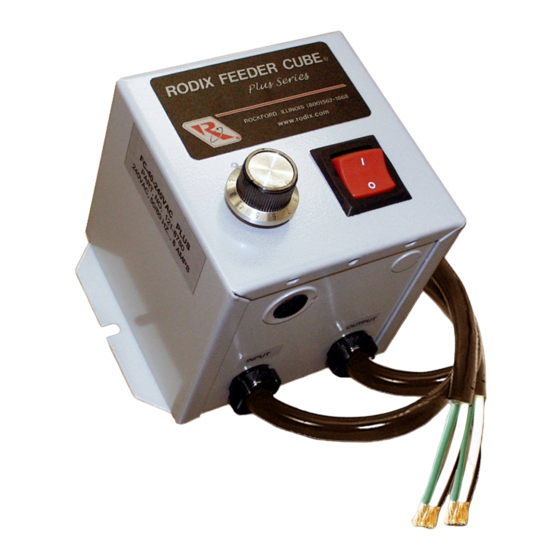
RODIX INC.
FEEDER CUBE
FC-40 Plus Series
Plus Series
Plus Series
Plus Series
GENERAL PURPOSE
MODEL FC-40-240-PLC Plus
P/N 121-8803
Listed, File No.
E183233
Input: 240 VAC
50/60 HZ.
Output: 0-240 VAC
Single Unit Fuse Size: 8 AMPS
© 2004, 2005 RODIX
INC
ADJUSTMENTS AND
1. SELECTING 60 OR 120 PULSE
A. For 60 pulse output - Set switch (S1) to 60 on
"master control" P.C. card (No. 24-489).
B. For 120 pulse output - Set switch (S1) to 120
on "master control" P.C. card.
Note: Readjust MAX pot after changing pulse
switch setting.
2. LIMITING THE MAXIMUM
OUTPUT OF CONTROL
Adjust the MAX Output trimpot so that the output
to the feeder reaches its desired maximum level
when the MAIN CONTROL DIAL is turned fully
clockwise. The MAX Output trimpot should be
adjusted to keep the vibratory feeder from
hammering when the control is turned up to full
power.
Plus
Plus
Plus
NOTE: Output to feeder must be connected
and the control set for proper output frequency
(60 or 120 pulse) setting. The Run Jumper
must be connected as shown on the wiring
diagram.
A. Power input should be OFF or disconnected.
B. Rotate MAIN CONTROL DIAL on front cover
to 0 or its minimum setting.
C. Open cover to allow access to printed circuit
card.
D. Using CAUTION, turn power ON (no output
should be present).
E. Rotate the MAIN CONTROL DIAL on front
cover slowly to its highest setting.
.
SET UP
OPERATION
F. Adjust the MAX Output trimpot so that the
output to the feeder reaches its desired
maximum level when the MAIN CONTROL
DIAL is turned fully clockwise. Turning the
MAX Output trimpot clockwise increases the
maximum output level.
3. REMOTE OFF/ON CONTROL
Note: a Run Jumper has been installed at the
factory as shown on the enclosed wiring diagram.
Remote OFF/ON operation of the FC-40 Plus
Series
Series
Series Feeder Cube
Series
control can be configured
®
to operate in one of the following ways.
A. A low current switch such as a paddle switch
can replace the factory-installed Run jumper
"J1."
The "Run Contact" connects to
terminals 6 and 7. The contact must be able
to switch 5VDC and 2mA. The control will
then run only when the contact is closed.
Refer to Section A of the OFF/ON CONTROL
GUIDE.
B. Feeder Bowl/Hopper Interlock allows the
Hopper control to operate only when the Bowl
is running and the paddle switch contact is
closed. The interlock input on terminals 11
and 12 of TB2 is controlled by the interlock
output of a "Parts Sensing Feeder Bowl
Control" such as an FC-90 Plus
Plus.
Plus
Plus
Remove jumper "J1" of this control from TB2
terminals 6 and 7.
Connect the Hopper
Paddle switch to alternate terminals 5 and 6 of
TB2. Connect TB2 terminals 11 and 12 of this
control to the "Parts Sensing Control". Refer
to Section B of the OFF/ON CONTROL
GUIDE. Check specific instructions for the
"Parts Sensing Control" wiring.
Note: Only use the Bowl/Hopper Interlock with
a FC-90 and FC-40 Series control. Two FC-
40 Series controls will not interlock to each
other since neither one has an interlock
output.
40-240-plc.doc 4/5/2005 Page 1
Plus
Plus
Plus
Advertisement
Table of Contents

Related Manuals for Rodix FEEDER CUBE FC-40 Plus Series


Summary of Contents for Rodix FEEDER CUBE FC-40 Plus Series
- Page 1 40 Series controls will not interlock to each should be present). other since neither one has an interlock E. Rotate the MAIN CONTROL DIAL on front Single Unit Fuse Size: 8 AMPS output. cover slowly to its highest setting. 40-240-plc.doc 4/5/2005 Page 1 © 2004, 2005 RODIX...
- Page 2 ON when the DC signal is present at terminals feature, remove resistor R4 from the bottom of the If under Warranty, Rodix will repair or replace your 11 and 12 of TB2. This input is optically board with a pair of pliers, twist R4 to snap it off.
- Page 3 105-250 VAC INPUT VOLTAGE OFF/ON CONTROL POWER FC-40 PLUS SERIES TERM STRIP TB-2 TRIAC REFERENCE GUIDE OUTPUT POWER INPUT POWER CHASSIS MODEL INPUT VAC AMPS OUTPUT GATE FC-40-240-PLC Plus Plus Plus Plus 240VAC 0-240 2004 RODIX Inc. FC42-240plc.doc 4/5/2005 Page 3...
- Page 4 Rodix controls have been designed with a AUX output. The shield “drain” wire high degree of immunity to electrical RECTIFIER should be tied to the chassis in the Rodix noise; however, depending on the control RELAY DIODE control. The drain wire should be kept...
Need help?
Do you have a question about the FEEDER CUBE FC-40 Plus Series and is the answer not in the manual?
Questions and answers