Advertisement
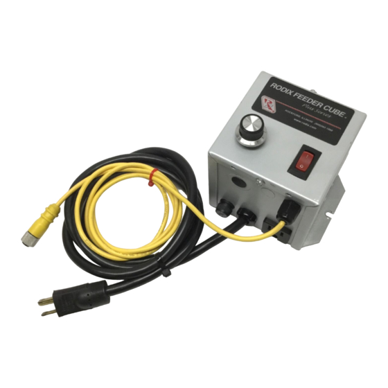
RODIX INC.
FEEDER CUBE
FC-200 & CFR-90
OPTION P/N 123-170
Plus
FC-200 & CFR-90
Control with Constant Feed Rate
Option
1.375
P/N 123-170
Fig. 2 The arrow shows the direction of vibration
which is at a right angle to the spring pack.
Warning: Avoid dropping the sensor before
installation. Dropping the sensor on a hard
surface could damage it and void the warranty.
© 2000, 2019 RODIX
INSTALLATION AND
Plus
Series
1. GENERAL DESCRIPTION
Vibratory feeders are inherently unstable and are
very susceptible to changes in part load and power
line voltage fluctuations.
cause part jams or very few parts to be fed to the
machine.
Sensitive
corrects for fluctuations in the vibratory feeder
Axis of
speed by using a sensor attached to the feeder to
Vibration
monitor the vibration level. The control then keeps
the vibratory feeder operating with a constant
amount of vibration and thus a constant part feed
rate.
Fig. 1
Actual Size
When something has caused a large change in
vibration, an approximate feed rate is restored
almost immediately. Then, the preferred feed rate
can be fully restored within a couple seconds.
Small changes in vibration are usually corrected
without the operator even knowing that a change
has occurred.
The sensor design incorporates a 4-20mA style of
output to provide immunity to electrical noise.
2. INSTALLING THE SENSOR
Note: Failure to adequately prepare the
feeder's surface properly may result in a
sensor that will not bond to the feeder. The
sensor will not be mounted until step C-6.
A. ORIENT THE SENSOR so that its sensitive
axis is in the same direction as the vibration of the
feeder. The double-ended arrow in figure 1 shows
the sensor's sensitive axis. Align the sensitive axis
of the sensor in the same direction as the vibration
(see figure 2). The sensor must be oriented
correctly for proper operation.
.
INC
OPERATION
These changes can
The Constant Feed Rate feature
B.
CHOOSE A LOCATION for mounting the
sensor on the feeder that is smooth and that will
allow the adhesive on the sensor to bond. Avoid
mounting the sensor over ridges and bumps which
can reduce the ability of the adhesive to stick to
the feeder. The correct location will also have
enough space for the sensor's cable to hang
straight down without touching anything else.
C. SURFACE PREPARATION of the feeder is
crucial for proper bonding between the sensor and
the feeder. Please follow these steps completely.
1) The feeder should be kept between 70 and
100 F for ideal tape application.
2) Clean a three and one-half inch circular area
with a solvent like isopropyl alcohol that will not
leave a residue. As a rule of thumb, the area
can be considered clean when after cleaning the
area with a solvent-saturated, white paper-towel,
the towel is as clean as it was before wiping.
3) Using a good amount of pressure, polish the
cleaned, circular area of the feeder using a
scratch pad or steel wool. Repeat step 2, and
then go to step 4.
4) Wipe the cleaned surface with an alcohol wipe
or with a 50/50 isopropyl alcohol/water
combination.
5) Air dry or dry the surface thoroughly using a low
lint cloth or a clean paper towel.
6) Remove the vibration sensor from its protective
packaging. Remove the liner from the adhesive
backing. Avoid touching the tape. Apply the
vibration sensor to the prepared area of the
feeder. Press the sensor very firmly onto the
feeder surface for at least 10 seconds.
7) Allow the vibration sensor at least 20 minutes to
cure before operation. Note: It takes 72 hours
for the adhesive to fully cure at 70 F.
Alternatively, #8 or M4 screws can be used to
mount the sensor to the feeder. The hole centers
are 1.375" apart.
D. ROUTE THE SENSOR CABLE to protect it
from strain due to vibration.
attaches to the sensor will not break from normal
vibration; however, some care should be used
when routing the wire from the sensor to the
control.
123-170 CFR 1-17-2019.doc 1/17/2019
The cable that
Advertisement
Table of Contents

Related Manuals for Rodix FC-200 Plus Series


Summary of Contents for Rodix FC-200 Plus Series
- Page 1 (see figure 2). The sensor must be oriented control. correctly for proper operation. © 2000, 2019 RODIX 123-170 CFR 1-17-2019.doc 1/17/2019...
- Page 2 3. TO LIMIT THE MAXIMUM In rare instances the Rodix control may not because the control may be regulating at a different maintain a tight enough tolerance of the vibration. If OUTPUT OF CFR-90 CONTROL: power level than is indicated by the main pot.
Need help?
Do you have a question about the FC-200 Plus Series and is the answer not in the manual?
Questions and answers