Table of Contents
Advertisement
SCS/SCS
gateway
Description
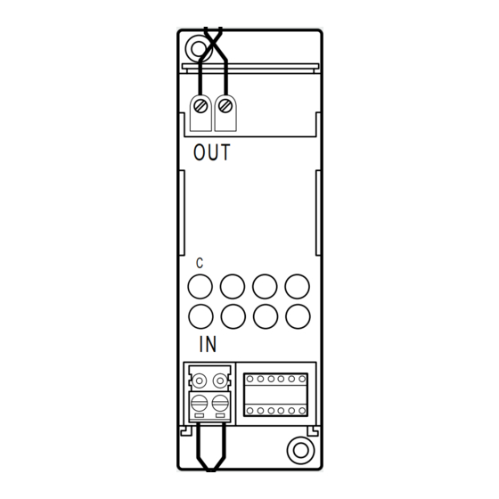
The gateway is an interface that provides communication among different BUS systems.
The interface has two BUS clamps, IN and OUT. On the front is a C key for virtual configu-
ration and a LED for the notification of:
- correct power supply and configuration (ON steady)
- BUS not detected (OFF)
- configuration not detected or incorrect configuration (flashing).
The device may operate in six different modes:
- Physical expansion: can increase the total BUS length or exceed the current draw limit
of 1200 mA for the individual power supply unit.
- Logical expansion: can increase the number of devices of a system, which is 175 (max 11
in rooms defined with A = 0 to 10 and 16 light points with PL = 0 to 15).
Address A = 0, PL = 0 is not permitted.
- Burglar alarm/automation interface: it allows communication between these two sys-
tems.
- Public riser: it provides alarm event supervision for the common parts of the video door
entry system.
- Galvanic separation: can interface two different functions (eg: Sound System with Au-
tomation).
- Physical separation: brings together the features of the Physical expansion mode and
the Galvanic separation mode. It can be used for systems with devices preset for virtual
configuration.
NOTE: Regardless of the interface mode of use, it must be taken into account that
the two Buses connected constitute at all effects two systems, and, as such, they
must be subjected to all existing sizing and installation rules.
Technical data
Power supply via SCS BUS:
Operating power supply with SCS BUS:
IN clamp current draw:
OUT clamp current draw:
Dissipated power with max. load:
Dimensions
Size: 2 DIN modules
Configuration
The interface is configured only with the physical configuration.
I1 I2 I3 I4 MOD
1) "Physical expansion" operating mode - configurator MOD = 1 -
With the interface configured in this mode, it will be possible to extend the physical limit
of the maximum length of the BUS, or exceed the limit of 1200 mA delivered by the indi-
vidual power supply, but not the maximum number of actuators (max. 175). The positions
identified with I1 and I2 must not be configured. The "separation address" between the
two buses connected to the interface must instead be defined in positions I3 and I4. Sup-
posing as in the example that I3=3, I4=2:
- On the input BUS (IN) the addresses must go from A=0 / PL=1 and A=3 / PL=1;
27 Vdc
18 – 27 Vdc
25 mA
5 mA
1 W
MQ00280-e-EN
5
OUT
C
4
3
IN
2
Legend
Configurator socket
1.
BUS
2.
Signalling LED
3.
4.
Button for future use
OUT clamp
5.
Sockets l1, l2, l3, and l4 are used to uniquely identify, using numerical configurators, the
addresses of the interfaces inside the system.
- On the output BUS (OUT) the addresses must be between A=3 / PL=3 and A=9 /PL=9 or
the address of the next interface. As it can be seen from the example, all the automation
BUS 1 addresses are lower than that of the interface, while all the automation BUS 2
addresses are higher; the interface address therefore separates all the addresses of which
the complete system might be made up of into two or more blocks.
07/06/2014
F422
1
1
Advertisement
Table of Contents

Related Manuals for LEGRAND Bticino SCS


Summary of Contents for LEGRAND Bticino SCS
-
Page 1: Technical Data
SCS/SCS gateway F422 Description The gateway is an interface that provides communication among different BUS systems. The interface has two BUS clamps, IN and OUT. On the front is a C key for virtual configu- ration and a LED for the notification of: - correct power supply and configuration (ON steady) - BUS not detected (OFF) - configuration not detected or incorrect configuration (flashing). - Page 2 SCS/SCS gateway F422 Installation example A/PL = 33 53 A/PL = 78 175 (*) Automation Automation = – = – = – = – = – = – MOD = 1 MOD = 1 MOD = 1 A/PL = 55 76 A/PL = 01 ...
- Page 3 SCS/SCS gateway F422 2) “Logic expansion” operating mode - configurator MOD = 2 This mode enables separation of control systems, with each of them therefore capable A typical example may be a large villa on several floors: A system may be installed for of using all the addresses available.
- Page 4 SCS/SCS gateway F422 3) “Public riser” operating mode - configurator MOD = 3 This mode is indicated when display of burglar alarms and technical alarms are required, generated within the common sections, using a switchboard, item 346310, installed on the backbone or the riser of the video door entry system. Simple diagram for the display of alarms on common parts Riser 1 Riser 2...
- Page 5 SCS/SCS gateway F422 4) “Interface between burglar alarm and automation/video door entry system/ 5) “Galvanic separation” operating mode sound system” mode - configurator MOD = 4 - configurator MOD = no configuration This mode can be used to interface the Automation system to the burglar alarm system, This configuration enables keeping the power supplies of the two buses separate, allow- to facilitate interaction and exchange of information between the two BUS.
- Page 6 SCS/SCS gateway F422 6) “Physical separation” mode - configurator MOD=6 This mode brings together the features of the “physical expansion” mode and the “gal- In view of the above, it will no longer be necessary to indicate the system separation vanic separation”...
- Page 7 SCS/SCS gateway F422 The use of the interface with this mode may be useful to keep the Automation system and the Temperature control system separate (for example when using independent power supplies). Automation = – = – = – MOD = 6 Energy management Installation rules:...
- Page 8 SCS/SCS gateway F422 7) Use of interfaces with different modes For home automation systems of a certain complexity, several systems may be integrat- If necessary, each of these can be expanded (physical expansion mode) or interfaced ed with interfaces configured in different modes. For example, it is possible to create with the Video Door Entry System or the Sound System using other interfaces.
-
Page 9: System Sound
SCS/SCS gateway F422 Example no. 2: system with logic expansion A/PL = 01 31 A/PL = 33 53 A/PL = 55 175 Automation Automation Automation (low addresses) (intermediate addresses) (high addresses) = – = – = – = –... - Page 10 SCS/SCS gateway F422 Example no. 3: system without logic expansion A/PL = 33 53 A/PL = 55 175 Automation Automation (intermediate addresses) (high addresses) = – = – = – = – MOD = 1 MOD = 1 A/PL = 01 ...
Need help?
Do you have a question about the Bticino SCS and is the answer not in the manual?
Questions and answers