Sign In
Upload
Download
Table of Contents
Contents
Add to my manuals
Delete from my manuals
Share
URL of this page:
HTML Link:
Bookmark this page
Add
Manual will be automatically added to "My Manuals"
Print this page
×
Bookmark added
×
Added to my manuals
Manuals
Brands
BMW Manuals
Engine
N62 Series
Service training
BMW N62 Series Service Training
Course contents/background material
Hide thumbs
1
Table Of Contents
2
3
4
5
6
7
8
9
10
11
12
13
14
15
16
17
18
19
20
21
22
23
24
25
26
27
28
29
30
31
32
33
34
35
36
37
38
39
40
41
42
43
44
45
46
47
48
49
50
51
52
53
54
55
56
57
58
59
60
61
62
63
64
65
66
67
68
69
70
71
72
73
74
75
76
77
78
79
80
81
82
83
84
85
86
87
88
89
90
91
92
93
94
95
96
97
98
99
100
101
102
103
104
105
106
107
108
109
110
111
112
113
114
115
116
117
118
119
120
121
122
123
124
125
126
127
128
129
130
131
132
133
134
135
136
137
138
139
140
141
142
143
144
145
page
of
145
Go
/
145
Contents
Table of Contents
Bookmarks
Table of Contents
Table of Contents
N62 Engine
Introduction
General Information
Technical Data
Full Load Graphs
Views of the N62 Engine
N62B36
N62 Supplement to Existing Documents
Crankcase Venting System
Alternator
Characteristic Mapping Thermostat
Engine Management
Vanos
Valvetronic System
N62 Engine Mechanics
Fresh Air System
Air Routing
Intake Manifold
Crankcase Venting System
Exhaust System
Structure
Exhaust Manifold with Catalytic Converter
Silencer
Secondary Air System
Ancillary Components and Belt Drive
Belt Drive
Alternator
Coolant Compressor
Starter Motor
Power Steering Pump
Cylinder Heads
Engine Cover
Cylinder Head Covers
Valve Gear
Valvetronic
Bi-VANOS (Variable Camshaft Adjustment)
Vacuum Pump
Chain Drive
Cooling System
Coolant Circuit
Water Pump
Map-Controlled Thermostat
Cooling Module
Cooling Radiator
Coolant Expansion Tank
Transmission Oil/Water Heat Exchanger (ÖWT)
Electrically-Operated Fans
Viscous Coupling Fan
Engine Block
Oil Sump
Crankcase
Crankshaft
Connecting Rod and Piston
Flywheel
Vibration Damper
Engine Suspension
Lubrication System
Oil Circuit
Oil Check Valve
Oil Pressure Switch
Oil Pump
Oil Filter
Pressure Control
Oil Cooling
Technical Data
N62 Engine Management System ME 9.2
Introduction
General Information
ME 9.2 Overview
Components
Functional Description
General Information
Oxygen Sensor Regulation
Oil Condition Sensor (OEZS)
Variable Intake Manifold
Idle Speed Control
Valvetronic
General Information
Function
Valvetronic Control Unit
DME Control Unit
DME Main Relay
Valvetronic Additional Relay
Valvetronic Motors
Valvetronic Sensors
N62 Fuel System
General Information
Injection Valves
Fuel Pressure Regulator
Electric Fuel Pump (EKP)
EKP Regulation
E65 Fuel Systems
General Information
Filling the Tank
Tank Ventilation
Fuel Supply System
Fuel Tank Leak Diagnostic Module
General Information
Function
Diagnostic Procedure
Glossary
Advertisement
Quick Links
1
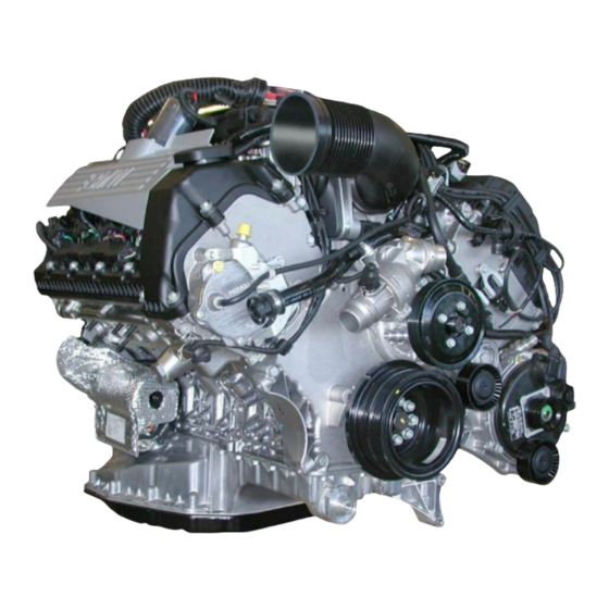
Views of the N62 Engine
Download this manual
New Generation N62 Engine
Course Contents/Background Material
Information status:
April 2001
BMW
Service Training
Table of
Contents
Previous
Page
Next
Page
1
2
3
4
5
Advertisement
Table of Contents
Need help?
Do you have a question about the N62 Series and is the answer not in the manual?
Ask a question
Questions and answers
Subscribe to Our Youtube Channel
Related Manuals for BMW N62 Series
Engine BMW N62B44 Manual
(55 pages)
Engine BMW N73B60 Workbook
(23 pages)
Engine BMW N55 Manual
(100 pages)
Engine BMW N63 Technical Service
(17 pages)
Engine BMW N62B36 Service Training
Course contents/background material (145 pages)
Engine BMW N13 Technical Training Manual
(92 pages)
Engine BMW M57 Service Training
Common rail, course contents/background material (64 pages)
Engine BMW D7 Workshop Manual
Marine (46 pages)
Engine BMW Advanced Car Eye 3.0 User Manual
(15 pages)
Engine BMW B58TU Reference Manual
(41 pages)
Engine BMW K25 R1200GS Parts Manual
(143 pages)
Engine BMW B46TU Reference Manual
(42 pages)
Engine BMW S58 Owner's Handbook Manual
(102 pages)
Engine BMW 745i Repair Instructions
Test and repair instructions for supercharged engine (95 pages)
Engine BMW B130 Workshop Manual
Marine engine (60 pages)
Engine BMW S63TU Product Information
Bmw s63tu engine (82 pages)
This manual is also suitable for:
N62b44
N62b36
Table of Contents
Save PDF
Print
Rename the bookmark
Delete bookmark?
Delete from my manuals?
Login
Sign In
OR
Sign in with Facebook
Sign in with Google
Upload manual
Upload from disk
Upload from URL


Need help?
Do you have a question about the N62 Series and is the answer not in the manual?
Questions and answers