
Related Manuals for BMW D7


Summary of Contents for BMW D7
- Page 1 Workshop Manual BMW D7 BMW Marine This copy of the BMW D7 Workshop Manual has been re-created using images computer scanned from a manual rather than original artwork.
- Page 2 Notes on Use This workshop manual describes complete procedures for dismantling, overhaul and assembly of the BMW D7 marine engine. If only part of the procedure is to be carried out (e.g. small repairs or replacement of gaskets, oilseals) the remainder can be ignored.
-
Page 3: Table Of Contents
Contents Page Page Introduction Fuel System Remove, adjust: Summary - Injection valve - Injection pump Removing cylinder head - Engine speed - Preparations Check: - Valve mechanism - Injection pump - Valves - Injection valve - Cylinder head - Fuel pump - Cylinder Air filter Removing gearbox... -
Page 4: Technical Data
Oil capacity, engine 2 litres / 3.5 pints UK / 4.4 pints US gearbox 0.4 litres / 0.7 pints UK / 0.85 pints US Fuel filter BMW 13 32 1 328 270 Air filter BMW 13 71 1 329 269 Injector Bosch... - Page 5 List of Special Tools D7 BMW Part No. Description 74 64 1 333 525 To refit ball hub 74 64 1 333 526 To refit crankshaft gear 74 64 1 333 513 Crankshaft installation tool 74 64 1 333 514...
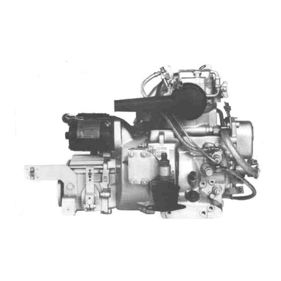
- Page 6 Summary BMW Marine Diesel Engine D7 Description: Water cooled single cylinder four stroke producing 4.5 kW (DIN) (6 Hp) Cylinder head cover Decompression lever Throttle cable mount Hand crank attachment Cover Sea water pump Fitting Hose clips Sea water hose 10.
- Page 7 Summary 21. Exhaust 22. Starter 23. Retainer yoke 24. Gear box 25. Crankcase 26. Fuel pump 27. Fitting 28. Sea water pipe CAUTION To avoid damage to engine parts, always use special tools as shown in the illustrations. The tools to be used fit only in the position shown. General...
-
Page 8: Removing Cylinder Head
Cylinder Head Removing cylinder head and cylinder CAUTION Remove air filter (1) Loosen sea water pipe from exhaust manifold Cover all openings in the fuel system and water pump and remove (2) + (3) Disconnect fuel return hose from injector and remove (4) Disconnect fuel injection pipe from injector and injection pump and remove (5) - Page 9 Cylinder Head Remove rocker shaft with bushing and retainer yoke and remove rockers (8) and (9) Pull out both pushrods Cylinder Head Repair Data D7 nominal Max. allowable Dimension Remarks values wear (mm) Rocker arms 0.05 -0.027 shaft dia. +0.024 Rocker arm 0.05...
-
Page 10: Valves
Cylinder Head, Timing Gear Remove decompression lever from the underside of the cylinder head (10) Unscrew the M10 nut and unscrew stud bolt. Remove the spring Remove retaining pin with pointed pliers Unscrew inner clamping sleeve on gear segment and remove shaft and gear segment. Remove valves &... - Page 11 Cylinder Head The valves should sit back as measured from the seating surface of the cylinder head, according to the following table: Repair Data Valves D7 nominal Max. allowable Cylinder Head Dimension Remarks values wear (mm) Valve clearance 0.15 cold Intake valve stem -0.04...
-
Page 12: Cylinder Head
Measure cylinder bore with a cylinder indicator In the following cases, the cylinder is unusable: Seize marks are found in the bore Scratches are present Wear exceeds 0.15 mm Repair Data Cylinder D7 nominal Max. allowable Cylinder Dimension Remarks values... -
Page 13: Starter
Bearing cover Remove starter (13) Remove attaching clamp of the cable to the stator and remove starter Remove the four cyclinder screws M 10 and remove the flywheel (15) and (16) Remove gearbox (14) complete with flywheel cover. Remove bearing cover Detach... -
Page 14: Bearing Cover
Bearing cover NOTE After loosening the four M6 hex screws, remove Bearing cover can be replaced when the engine is the bearing cover with locking plate and the cold sealing ring located on the inner face (17) Remove bearing cover Detach... -
Page 15: Hand Crank Mechanism
Cover to timing gear cover / timing gear cover / hand cranking device Remove screws from cover of timing gear cover and take off the cover (18) Remove hand crank mechanism (19) with extractor tool No 666 332 00 Detach Cover of timing gear cover, hand crank device, dipstick, cover on engine bottom, Remove connecting rod... -
Page 16: Connecting Rod
Dipstick / cover on engine bottom / connecting rod Turn the engine on to the flywheel side (23) and remove dipstick (24) Remove cover and O-ring from crankcase on the engine bottom (25). Unscrew the two connecting rod screws (26). Take out connecting rod cap with oil pick-up (27) from below and piston and connecting rod (28) from top. - Page 17 Table: Repair data for connecting rod and connecting rod bearing Repair Data for con-rod bearing and con-rod D7 nominal Max. allowable Con-rod bearing Dimension Remarks values wear (mm) Outer dia Minimum bearing play = 0.040-0.076mm when new +0.016 Inner dia see table on page max wear to 0.15mm...
-
Page 18: Piston
(29). piston scuffed ring groove worn out and cracked Piston rings are unusable when the gap is too Repair Data D7 nominal Max. allowable Piston Dimension Remarks values wear (mm) Piston dia 72.96... -
Page 19: Fuel Pump
Fuel pump / timing gear cover Remove fuel pump (29a) Remove pump plunger (29b) Unscrew the three M16 hex nuts and remove timing gear cover (29c) Detach Fuel pump, pump plunger, timing gear cover Remove... - Page 20 Withdraw regulator lever with regulator spring (29i) Turn engine on flywheel side. Repair Data for Regulator Spring Washers Maximum rpm No of balls Regulator Spring BMW Part No Wire Dia 3600/160 13 41 1 329 652 Remove Regulator lever with regulator spring...
-
Page 21: Crankshaft
Ball sleeve / Crankshaft Remove ball sleeve with sliding disc taking care that no balls fall out (30) Ball hub and spacer washer (31) remain on crankshaft. Detach these parts only when removing the crankshaft. Turn the engine block into the horizontal position. Removing the crankshaft NOTE It is essential that all plastic parts such as oil filler... -
Page 22: Remove Crankshaft
Crankshaft The outer race of the straight roller bearing on the timing gear side remains in the crankcase and can be removed with the aid of a press In order to remove the bearing rings which have been shrunk on to the crankshaft (35) heat the crankshaft on a heating plate or with a sufficiently large gas burner rapidly to about 70 to 80 After removal of the M8 cylinder head screws,... - Page 23 Table: Repair data for crankshaft Repair Data for Crankshaft D7 nominal Max. allowable Crankshaft Dimension Remarks values wear (mm) -0.060 Crank pin dia 42.0 Total play 0.15 max Max allowable crank pin -0.070 out-of-round 0.05mm End float +0.068 Crankshaft crank 33.0...
-
Page 24: Valve Lifters
Valve lifters and camshaft Remove the plastic plug from the side of the engine block (37) Unscrew the M8 set screw (38) with a 4 mm Allen key and remove together with plug CAUTION When removing the camshaft, lift off both rockers from the camshaft to prevent damage by the cam lobes Pull out valve rocker shaft with the aid of... -
Page 25: Camshaft
Camshaft Crankshaft Reassembly of the engine parts is carried out in the reverse order. Installing the crankshaft Attach the counterweights, tightening the bolts to a torque of 2.2 kg/m (16 lb/ft) Heat the inner race of the roller bearing to NOTE between 70 and 80 C and mount on the... -
Page 26: Timing Gear Cover
Fuel Regulator / Gear on the Crankshaft Connecting Rod Timing gear cover / Fuel pump Crankcase cover / dipstick / bearing cover Set the engine block into the horizontal position Install connecting rod in such a manner that the scoop is filled through the scoop opening when Insert regulator lever and regulator spring Insert clamping sleeve into the regulating spring dipping into the lubricating oil. -
Page 27: Reversing Gear
Seal locking screws in the oil space of the cylinder head with a permanently elastic sealing compound (e.g. Atmosit or similar) Repair Data Cylinder Head Dimension D7 nominal values Piston gap (A) 0.55 – 0.65 Cylinder head (b) 1.50 gasket... -
Page 28: Cylinder Head
Cylinder head / Injection pipe / Leak-off-line / Water pump / Water hose / Air filter Press in valve guides from underneath Insert valves Insert valve springs with cap and washer Insert spring plate Insert both valve keys, while applying counter pressure to the valve Insert shaft with gear segment and screw in internal clamping sleeve. -
Page 29: Adjust
Repair Data Valves D7 nominal Max. allowable Cylinder Head Dimension Remarks values wear (mm) Valve clearance 0.15... -
Page 30: Decompression Lever
Decompression lever adjustment If the engine is not decompressed in Position “1” of the decompression lever, adjust the decompression screw as follows: Crank the engine to the same position as in the valve adjustment Turn the decompression lever to Position “1” After loosening the hex nut, turn the adjusting screw to the right until the rocker arm touches the valve shaft... - Page 31 Timing gear adjustment Correction is required in the following cases: If the collar pan constantly engages the cog lightly, in the case of running the engine and zero position of the decompression lever (Shaft moves back and forth) In this case, shorten the tappet somewhat and dimension “A”...
-
Page 32: Fuel System
Injection Pump Bosch type code PFE 1Q 55/19 With second hole in housing Bosch No 0 414 050 996 (for automatic venting) BMW Part No 1351 1329 656 Injector Assy Bosch type code Bosch No 0432 297 022 BMW Part No... - Page 33 Injection pump Adjust the injection pressure by inserting or Injector overhaul removing shims at the injector spring Extreme cleanliness is necessary during work on NOTE injector. A shim with a thickness of 0.1 mm Unscrew sleeve nut F (22 mm) and withdraw changes the pressure by approx.
-
Page 34: Injection Pump
Injection pump Preliminary tasks before removing the injection The start maximum fuel eccenter must be turned in pump: such a manner that the eccentric arm points vertically upward before installing the injection pump. The injection pump has two hose connectors and a pipe connection. - Page 35 Injection pump NOTE Preliminary work: Slide the pump in to about the last 4 mm Clamp off the fuel supply line without overcoming any resistance. Only Unscrew injection pump pressure valve holder. then may resistance occur due to the Remove spring, sealing ring, valve cone and tension of the tappet spring pressure valve (see figure) Screw in adjusting device No 74 64 1 333 535...
-
Page 36: Engine Speed
Injection pump Adjustment of the delivery end: After the adjustment is completed remove the dial indicator and install the completely Crank the engine in the direction of rotation until assembled delivery valve with injection pipe in the fuel stops to flow from the adjustment device the correct sequence. -
Page 37: Check Injection Pump
Injection pump / Injector Venting Injection pump Fuel pump NOTE WARNING Carry out the check with the throttle in the Danger of injury due to the fuel jet fully open position and with the starting filling not pulled. As the engine has automatic fuel system venting, the necessity for a manual venting does not apply, as After installing the testing device No the trapped air in the injection pump escapes... -
Page 38: Air Filter
Air filter Cleaning the air filter Loosen clips. Remove filter element. Remove sealing ring from cover and clean groove Install new sealing ring and filter element. NOTE Never use an old filter element Clean air intake openings and pipe in the filter NOTE Premature engine wear occurs if unfiltered or badly filtered air is drawn... -
Page 39: Wiring Diagram
Wiring diagram... -
Page 40: Preparations
Generator and generating equipment Preparation Generating Equipment Removal Remove starter motor Disconnect leads from temperature sensor and Detach gearbox/clutch cover assembly remove stator cable plug C from socket on Remove clutch equipment carrier Remove flywheel Remove bolts D (13 & 19 mm), noting position of spacers, washers and injector pipe clip (if Rotor Removal fitted) and remove carrier and equipment... -
Page 41: Generator
Generator and generating equipment Flatten lockwasher/cable clip F (renew on Lay stator harness close to bearing housing, to assembly), securing stator cable to bearing avoid contact with flywheel housing (SW 13) Bend tags of stator cable end slightly to ensure Remove bolts G (7 mm) and lift off stator firm fit before fitting to plug. - Page 42 Generator and generating equipment Checking Procedure 1 – Impulse Transmitter When no or insufficient charge are shown, control unit and/or generator are defective Thin red lead of impulse transmitter earths control For further fault location, voltage between each lamp when engine is stationery. When charge from of the 2 black leads, red lead and generator control unit passes through transmitter, this earth is should be checked.
- Page 43 Generator and generating equipment If reading is not adequate, whereby reading of leads 1 and 2 are different, there are 2 possibilities: - when both leads lie below the correct reading, rotor magnetism is inadequate and rotor should be replaced - when only one lead shows a low reading, a fault in the stator windings is indicated and the stator should be renewed.
-
Page 44: Starter Motor
Starter Motor Starter Motor Removal Disconnect cables A from solenoid (connector 19mm) and remove insulation B Remove fixing nuts C (19mm) and detach earth strap D from upper stud Lift off starter motor When faulty renew. - Page 45 Water pump Service Instructions A. Disassembly B. Assembly Remove cover screws, cover and gasket Press the ball bearings on to the shaft. Do NOT Press out impeller with 2 screwdrivers press the ball bearings over the sealing surface After removing the cam, remove residual traces of the shaft of sealing compound from cam and pump Press the shaft with ball bearings into the pump...
-
Page 46: Water Pump
Water pump Waterpump Sea water pump 12. O-ring Cheese head screw M4 x 8 13. Deep groove ball bearing Cover 14. Snap ring Seal 15. Shaft Impeller 16. Clamping sleeve Cheese head screw 17. Stop screw Washer 18. Hex head nut M6 19.
Need help?
Do you have a question about the D7 and is the answer not in the manual?
Questions and answers