
Related Manuals for Pepperl+Fuchs FYQLA1-140R-3


Summary of Contents for Pepperl+Fuchs FYQLA1-140R-3
- Page 1 FACTORY AUTOMATION INST R UC TI O N M A N UA L Door Interrupt System With FYQLA1-140R-3 Logic Amplifier Original Instructions...
-
Page 2: Table Of Contents
Contents Introduction ...................... 3 Declaration of conformity .................. 4 Information regarding EC conformity ..............4 Document purpose .................... 4 Scope ......................4 Delivery ......................4 Definitions ....................5 Symbols used ....................5 ................. 5 General statements Qualified personnel ..................5 Intended use .................... -
Page 3: Introduction
The company Pepperl+Fuchs, Inc. claims copyright on this documentation. To modify, extend, hand over to a third party, or copy this documentation without written approval by the company, Pepperl+Fuchs, Inc. is expressly prohibited. Nor is any liability assumed for damages resulting from the use of the information contained herein. -
Page 4: Declaration Of Conformity
A corresponding declaration of conformity may be requested from the manufacturer. Note Information regarding EC conformity Pepperl+Fuchs declares that the product described in this manual conforms with EC Directives by providing the following information: Pepperl+Fuchs GmbH, Lilienthalstraße 200, 68307 Manufacturer Mannheim, Germany, www.pepperl-fuchs.com... -
Page 5: Definitions
The door interrupt system must be installed by qualified personnel who are properly trained in the installation and usage of the FYQLA1-140R-3 product. These persons must have access to all instructions and knowledge of all required safety requirements regarding the application of such devices and machinery equipment. -
Page 6: Intended Use
The FYQLA1-140R-3 must be used in accordance with its intended purpose. The system must be installed according to regulations for... -
Page 7: Product Description
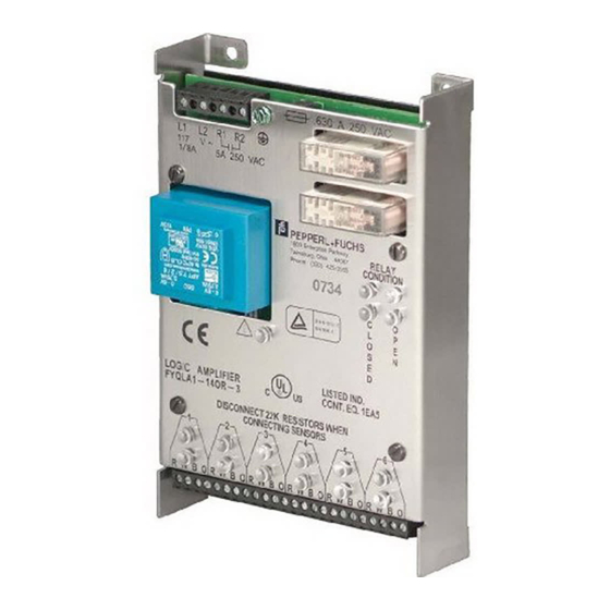
Features The FYQLA1-140R-3 is a category 3 PL d( ISO 13849-1:2015) logic amplifier. The basic features of the FYQLA1-140R-3 include inputs for up to six individual two-channel switches for monitoring door access or guarded/monitored functions. Both channels are monitored and cross checked for proper operational switch states. -
Page 8: Daily Inspection
Door Interrupt System with FYQLA1-140R-3 Logic Amplifier... - Page 9 Door Interrupt System with FYQLA1-140R-3 Logic Amplifier...
-
Page 10: Safety Inputs
These outputs must operate in tandem for a valid switch function to be recognized by the FYQLA1-140R-3. If the output channels of the switches are not functioning in a synchronized manner the amplifier will not accept the switch closure as a valid. -
Page 11: Indicators
Door Interrupt System with FYQLA1-140R-3 Logic Amplifier Indicators The FYQLA1-140R-3 has indicators on front of the device for the following functions: • State of the connected input switches ▸ Two indicators per switch input (channel A & channel B) ▸ Indicator is illuminated (on) when the switch state is open •... -
Page 12: Guided Relays
Door Interrupt System with FYQLA1-140R-3 Logic Amplifier Guided relays The door interrupt system incorporates two force-guided safety relays that are monitored for proper operation and generate a redundant output for application use. Input devices Magnetic switches The 50FY41 series hall effect door switches are a noncontact, magnetic actuation system consisting of a sensor and a magnetically keyed actuator. -
Page 13: Nominal Offset Distances
Door Interrupt System with FYQLA1-140R-3 Logic Amplifier Nominal offset distances Magnet actuator Sensing distance mm (in) Offset Distance Offset Max. Actuator Off Distance Hall effect sensor Distance 0 (zero) 2.5 (0.1) 10 (0.4) 3.8 (0.15) 1.3 (0.05) 10 (0.4) 7.5 (0.3) 0 (zero) 10 (0.4) -
Page 14: Installation
Panel mounted inside an enclosure using the four mounting feet in the stainless steel housing. The FYQLA1-140R-3 is intended to be installed in a clean and dry environment. A control cabinet must be used to guarantee that the unit is exposed to no worse than an IP20 environment. -
Page 15: Electrical Installation
Door Interrupt System with FYQLA1-140R-3 Logic Amplifier Electrical installation Switch the main machine power OFF prior to installation! The machine could inadvertently start during installation. The door interrupt system fulfills the EMC requirements in accordance with EN/IEC 61326-3-2:2008 for safety related systems. -
Page 16: Wiring Diagram
Door Interrupt System with FYQLA1-140R-3 Logic Amplifier Wiring diagram FYQLA1-140R-3... -
Page 17: Electrical Connection
Door Interrupt System with FYQLA1-140R-3 Logic Amplifier Electrical connection Monitor terminals 50FY41 Unused inputs R (positive) RED - positive Use two, 22 K W (normally open, sourcing) WHITE - output resistors B (negative) BLACK - ground (included) O (normally open, sinking) -
Page 18: Commissioning And Startup
Door Interrupt System with FYQLA1-140R-3 Logic Amplifier Commissioning and startup Do not commission without a check by qualified safety personnel! The door interrupt system must be installed by qualified personnel who are properly trained in the installation, application, and usage of the FYQLA1-140R-3 product. -
Page 19: Diagnostics
Door Interrupt System with FYQLA1-140R-3 Logic Amplifier Diagnostics Faults The door interrupt system has multiple LEDs mounted on the top of the device to provide diagnostic and troubleshooting assistance. LEDs are provided for each switch input pair, indicating the status of the individual channel. Also provided are output LEDs indicating the status of each of the safety relays. -
Page 20: Fault Diagnosis
Door Interrupt System with FYQLA1-140R-3 Logic Amplifier Fault diagnosis If fault LED flashes and no sensor alignment problem can be found: • Turn off power • Unwire sensors from input terminals • Power up unit • If fault LED begins to flash repeatedly after 2-3 seconds, the system needs to be replaced. - Page 21 Door Interrupt System with FYQLA1-140R-3 Logic Amplifier Product specifications (cont.) Functional safety related parameters* Safety function Relay output closed only when sensors activated by appropriate target Safe state Relay output open Standards/regulations ISO 13849-1 :2015/UL 508 Performance level acc. to ISO 13849-1 PL d Structure acc.
- Page 22 Door Interrupt System with FYQLA1-140R-3 Logic Amplifier Product specifications (cont.) Ambient conditions Operating temperature -25 °C to +70 °C noncondensing Storage temperature -25 °C to +70 °C noncondensing Terminal block - power and relays Conductor cross section capacity 0.2 mm² to 2.5 mm² (22 to 14 AWG) Cu Tightening torque 0.5 Nm (4.5 lb-in)
-
Page 23: Dimensions
Door Interrupt System with FYQLA1-140R-3 Logic Amplifier Dimensions (for reference only—dimensions in mm) 4X Ø 5.56 .630 A 250 VAC R1 R1 1/8A 5A 250VAC Twinsburg, Ohio 44087 RELAY Phone: (330)425–3555 CONDITION LISTED LOGIC AMPLIFIER IND. CONT. EQ. FYQLA1-140R-3 1EA5... - Page 24 North/Central American Headquarters Pepperl+Fuchs Inc. Twinsburg · Ohio · USA Tel. +1 330 486 0002 E-Mail: fa-info@us.pepperl-fuchs.com Subject to modifications • Copyright Pepperl+Fuchs • Printed in USA • TDOCT-B1Z0_ENG 09/18...
Need help?
Do you have a question about the FYQLA1-140R-3 and is the answer not in the manual?
Questions and answers