Sign In
Upload
Download
Table of Contents
Contents
Add to my manuals
Delete from my manuals
Share
URL of this page:
HTML Link:
Bookmark this page
Add
Manual will be automatically added to "My Manuals"
Print this page
×
Bookmark added
×
Added to my manuals
Manuals
Brands
Pepperl+Fuchs Manuals
Amplifier
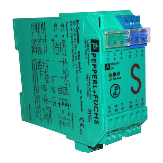
KFD2-SH-Ex1
Original instructions manual
Pepperl+Fuchs KFD2-SH-Ex1 Original Instructions Manual
Functional safety switch amplifiers
Hide thumbs
1
2
Table Of Contents
3
4
5
6
7
8
9
10
11
12
13
14
15
16
17
18
19
20
21
22
23
24
25
26
27
28
page
of
28
Go
/
28
Contents
Table of Contents
Bookmarks
Table of Contents
Table of Contents
1 Introduction
Safety Information
Symbols Used
2 Product Description
Function
Interfaces
Marking
Standards and Directives for Functional Safety
3 Planning
System Structure
Assumptions
Safety Function and Safe State
Characteristic Safety Values
Useful Life Time
4 Mounting and Installation
Configuration
5 Operation
Proof Test Procedure
6 List of Evaluated Sensors
7 Maintenance and Repair
8 List of Abbreviations
Advertisement
Quick Links
1
Function
2
Interfaces
3
Mounting and Installation
4
Configuration
5
Operation
6
Proof Test Procedure
7
Maintenance and Repair
Download this manual
PROCESS AUTOMATION
ORIGINAL INSTRUCTIONS
Functional Safety
Switch Amplifier
KFD2-SH-Ex1(.T)(.OP),
KHA6-SH-Ex1
3
PL d
Table of
Contents
Previous
Page
Next
Page
1
2
3
4
5
Advertisement
Table of Contents
Need help?
Do you have a question about the KFD2-SH-Ex1 and is the answer not in the manual?
Ask a question
Questions and answers
Related Manuals for Pepperl+Fuchs KFD2-SH-Ex1
Amplifier Pepperl+Fuchs KFD2-GU-1 Manual
Temperature trip amplifier (24 pages)
Amplifier Pepperl+Fuchs KFD2-GU-Ex1 Manual
Temperature trip amplifier (24 pages)
Amplifier Pepperl+Fuchs KFD2-SR2-Ex1.W.LB Instruction Manual
(2 pages)
Amplifier Pepperl+Fuchs KFD2-SR2-Ex1.W Instruction Manual
Switch amplifier (2 pages)
Amplifier Pepperl+Fuchs KFD2-SR2-Ex Series Manual
Functional safety switch amplifier (24 pages)
Amplifier Pepperl+Fuchs KFD2-SOT3-Ex Manual
(24 pages)
Amplifier Pepperl+Fuchs KFD2-SR3-2.2S Manual
(20 pages)
Amplifier Pepperl+Fuchs KFD2-SR3-Ex2.2S Manual
(20 pages)
Amplifier Pepperl+Fuchs KFU8-SR-Ex1.W Instruction Manual
Switch amplifier (2 pages)
Amplifier Pepperl+Fuchs KFA4-SR2-Ex1.W Instruction Manual
Switch amplifier (2 pages)
Amplifier Pepperl+Fuchs SIL KFU8-SR-Ex W LB Series Manual
Switch amplifier (24 pages)
Amplifier Pepperl+Fuchs KHA6-SH-Ex1 Original Instructions Manual
Functional safety switch amplifiers (28 pages)
Amplifier Pepperl+Fuchs KCD2-SR-1.LB Safety Manual
Switch amplifier (20 pages)
Amplifier Pepperl+Fuchs KCD2-SR Series Manual
Functional safety switch amplifier (24 pages)
Amplifier Pepperl+Fuchs KCD2-SON-Ex Series Manual
Switch amplifier (22 pages)
Amplifier Pepperl+Fuchs KCD2-SON-Ex1 Manual
Switch amplifier (22 pages)
This manual is also suitable for:
Kfd2-sh-ex1.t
Kfd2-sh-ex1.op
Kha6-sh-ex1
Table of Contents
Print
Rename the bookmark
Delete bookmark?
Delete from my manuals?
Login
Sign In
OR
Sign in with Facebook
Sign in with Google
Upload manual
Upload from disk
Upload from URL


Need help?
Do you have a question about the KFD2-SH-Ex1 and is the answer not in the manual?
Questions and answers