
Related Manuals for ComNav P4


Summary of Contents for ComNav P4
- Page 1 ComNav P4 Autopilot Advanced Autopilot Systems Installation and Operation Manual PN 29010100...
-
Page 2: Welcome
Web: www.ComNav.com E-mail:sales@comnav.com service@comnav.com Warranty Prior to the installation and/or operation of any ComNav equipment, please take a moment to read and accept all warranty conditions as detailed in the Warranty Information section of this manual. WARNING This Autopilot is for navigation assistance only. Whenever underway, your... -
Page 3: About This Manual
About this Manual This manual provides essential information for the safe and reliable operation of the ComNav P4 Advanced Autopilot System. You are urged to read this manual in its entirety before you use your autopilot for the first time, and to keep it handy until you become thoroughly familiar with the operation of your autopilot. -
Page 4: Manual Format
ComNav P4 Installation and Operation Table of Contents, List of Figures and Tables Manual Format Date Description 16 August 2018 First Release This manual has been formatted to be printed on both sides of the pages, and on standard North American Letter-size paper (8.5” x 11”). -
Page 5: Document History
ComNav P4 Installation and Operation Table of Contents, List of Figures and Tables Document H istory Revision: Date: By: Description: 1R0 November 2 018 First R elease - 5 -... -
Page 6: Table Of Contents
ComNav P4 Installation and Operation Table of Contents, List of Figures and Tables Table of Contents Welcome ......................... 2 About this Manual ............................ 3 Typefaces, Common Phrases and Terms ....................3 Manual Format ............................4 Document History ............................ 5 Table of Contents ......................6 List of Figures ............................ - Page 7 ComNav P4 Installation and Operation Table of Contents, List of Figures and Tables Installation ..........................43 Basic Requirements ..............................43 Steering System ..............................43 Power Supply ................................43 Special Tools ................................43 Fasteners ................................. 43 Control Head ................................44 Electrical Connection ............................... 44 Signal Processor Unit ..............................
- Page 8 ComNav P4 Installation and Operation Table of Contents, List of Figures and Tables Getting Started ........................72 Autopilot Operations ..............................73 Power On/Of ................................73 Using the Control Head – LCD Screen and Buttons ....................75 Operating Modes and Menus ..........................76 Advanced Operations .............................
- Page 9 ComNav P4 Installation and Operation Table of Contents, List of Figures and Tables Basic Operations ......................... 122 Control Head LCD Screen and Buttons ......................... 123 Operating the System ............................125 Mode Menus ................................125 Rudder Angle Indicator ............................127 Power On ................................128 Power Off ................................
- Page 10 ComNav P4 Installation and Operation Table of Contents, List of Figures and Tables Advanced Operations ......................152 WORK Mode ................................ 153 Work Menu ................................156 Rudder Bias ................................. 156 Autotrim ................................156 Work Trip Pt. (Work Trip Point) ..........................156 Rudder Scale (Rudder Scale Factor) ........................
- Page 11 ComNav P4 Installation and Operation Table of Contents, List of Figures and Tables Compass Safe Distances ............................181 CE Compliance ..............................182 Warranty Information ............................. 183 Index ..................................187 User Notes and Settings ............................190 - 11 - Document PN 29010100 V1r0...
-
Page 12: List Of Figures
Figure 3 – P4 System Block Diagram ......................28 Figure 4 – Control Head ..........................29 Figure 5 – The P4 SPU with Wiring and Diagnostic Covers Removed ............30 Figure 6 – G2 GPS Compass ......................... 31 Figure 7 – Navigator G2 Display Head ......................32 Figure 8 –... - Page 13 ComNav P4 Installation and Operation Table of Contents, Lists of Figures and Tables Figure 50 – A Typical Menu ..........................81 Figure 51 – Set Vessel Type ......................... 104 Figure 52 – Set Compass Type ........................107 Figure 52a – Using the Control Head ......................123 Figure 53 –...
-
Page 14: List Of Tables
Table 6 – Nav Mode Correction ........................143 Table 7 – Fuse Replacement Guide ......................168 Table 8 – NMEA 0183 Sentences Accepted by the P4 ................172 Table 9 - NMEA Sentence Priority ........................ 173 Table 10 – Warning Messages ........................175 Table 11 –... - Page 15 ComNav P4 Installation and Operation Table of Contents, Lists of Figures and Tables - 15 - Document PN 29010100 V1r0...
- Page 16 ComNav P4 Installation and Operation Introduction - 16 - Document PN 29010100 V1r0...
- Page 17 ComNav P4 Installation and Operation - 17 - Document PN 29010100 V1r0...
-
Page 18: How Autopilots Work
There are a number of parameters used in the steering algorithms, collectively referred to as “Steering Parameters.” The P4 Autopilot system has been tested on a wide variety of boats, of different types and sizes. The default settings for the Steering Parameters are average values derived from that testing, and provide a good starting place for most boats. -
Page 19: Basic Autopilot System
ComNav P4 Installation and Operation How Autopilots Work Basic Autopilot System Figure is a block diagram of the major components of an autopilot system. NAVIGATION DEVICES CONTROL HEAD DISPLAYS STATUS AND HEADING [OPTIONAL] SUPPLY NAVIGATION INFORMATION FROM THE SPU, AND... -
Page 20: Autopilot Operation: Maintaining A Heading And Current Effects
“RFU”), a device that tells the SPU what position the rudder is in at any given time. Autopilot Operation Maintaining a Heading: AUTO Mode With a ComNav Autopilot, following a Track or Course that you want to be on is very simple: • Set the autopilot into AUTO mode. - Page 21 ComNav P4 Installation and Operation How Autopilots Work • On the other hand, if the boat is coming back too quickly, the rudder will be moved quickly back to dead-ahead – or maybe even a bit to Port for a few seconds.
-
Page 22: Figure 2 - Heading Change In Auto Mode
ComNav P4 Installation and Operation How Autopilots Work Changing Heading Heading changes are very simple with a ComNav autopilot as well. Imagine for example, that the autopilot is steering your boat Southwest, and you now wish to change direction to Southeast (see... - Page 23 Navigation System, or it may be another device or system, like a GPS receiver (such as a ComNav GPS Compass), a LORAN C receiver, etc. (all such external devices are in general referred to in this manual using the generic term Navigation System).
- Page 24 ComNav P4 Installation and Operation How Autopilots Work Cross and/or currents are compensated for automatically each time the Navigation System updates the Cross-Track Error. This is why NAV mode is the answer to the “track slip” problem that can occur in AUTO mode, when a cross/current exists.
-
Page 25: Power Steer
How Autopilots Work Following a Track: AUTO/ALC Mode Some ComNav autopilots (including the P4), provide another way to keep your boat on a specific Track: Automatic Leeway Correction. This feature can be turned on in AUTO mode. ALC is similar to NAV mode, in that it uses NMEA0183 or NMEA2000 Latitude and Longitude data to sense if the boat is following the desired Track. -
Page 26: System Overview
ComNav P4 Installation and Operation System Overview System Overview - 26 - Document PN 29010100 V1r0... - Page 27 System Overview System Overview This chapter provides a brief description of the major elements of the P4 Advanced Autopilot System, its functions, and their relationships to each other. shows a block diagram of a typical example of the P4 system, showing the...
-
Page 28: Figure 3 - P4 System Block Diagram
ComNav P4 Installation and Operation System Overview Figure 3 – P4 System Block Diagram - 28 - Document PN 29010100 V1r0... -
Page 29: Control Head
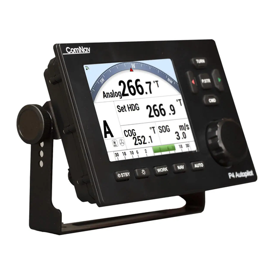
Figure 4 – P4 Control Head The Control Head, when shipped as part of a complete P4 system, is a “core” module, with accessories for mounting option: bracket for bracket mounting. All required hardware is included, except for two fasteners needed to fasten the bracket to a mounting surface. -
Page 30: Signal Processor Unit
ComNav Rudder Feedback, ComNav RAI, NMEA 0183 Interfaces and Rudder Drives and Interfaces). The P4 SPU connects to a NMEA 2000 network or standalone with a supplied T- connector to the P4 Head, via a supplied 1m NMEA 2000 (Pigtail & Male End) cable at the Network Port of the SPU. -
Page 31: Compasses
System Overview Compasses The Compass is a critical component in the proper operation of the P4 Autopilot System. The autopilot system’s ability to steer the vessel to a given Heading desired by the Operator can only be as accurate as the Compass. -
Page 32: Figure 7 - Navigator G2 Display Head
The GNSS NMEA0183 model is connected to the P4 Autopilot at one of the SPU’s two NMEA Input ports. The standard cable lengths are 15 metres (50’) or 30 metres (100’);... -
Page 33: Fluxgate Compass
8) connects the Display Head(s) to a GNSS G2/G2B, and has a convenient set of terminal strips for connecting power, the signals to and from it, as well as the signals to the P4’s SPU. It also has a connector for the cable to a PC’s COM port. Figure 8 –... -
Page 34: Magnetic Compass Sensor
The sealed unit can be attached to the bottom of any of ComNav’s Magnetic Compasses, or the bottom or top of many other brands of externally gimballed magnetic compasses. It is wired directly to the SPU, with the attached 25’... -
Page 35: Other Compasses
See your ComNav Dealer or consult the factory for information on interfacing these compasses with the P4 system. -
Page 36: Jog Levers
Rudder Angle Indicator (RAI) – 3” PN 20360023 The ComNav Rudder Angle Indicator (RAI) is a backlit 3” (76 mm) diameter gauge that displays the actual position of the vessel’s rudder. The RAI is flush mounted, encased in high impact resistant polycarbonate plastic with a water resistant front face, and requires a lighting voltage supply of 12, 24 or 32 VDC. -
Page 37: Figure 15 - External Rudder Angle Indicator - 3" Model
ComNav P4 Installation and Operation System Overview Figure 15 – External Rudder Angle Indicator - 3" Model - 37 - Document PN 29010100 V1r0... -
Page 38: Rudder Drives And Interfaces
It has standard voltage outputs, current loop outputs and optically-isolated analog outputs. The CT7 also contains circuitry for interfacing an Electric Wheel to the P4 system, and a Rudder Simulator which is used when the CT7 is interfaced to Azimuth Drives. -
Page 39: Other Drive Boxes
ComNav P4 Installation and Operation System Overview Other Drive Boxes The P4 system is capable of directly operating steering systems utilizing reversing DC motors or single speed solenoids. ComNav also manufactures a complete line of Drive Boxes that will interface the steering outputs from the P4 system to almost any type of steering system. -
Page 40: Pumps And Drives
ComNav P4 Installation and Operation System Overview Pumps and Drives ComNav offers several types of electric-motor Hydraulic Pumps, matching Solenoid Values and related equipment, as well as a number of high-quality Cable Drives and accessories. Each drive comes with its own Installation Manual. - Page 41 ComNav P4 Installation and Operation - 41 - Document PN 29010100 V1r0...
- Page 42 Installation ComNav P4 Installation and Operation Installation - 42 - Document PN 29010100 V1r0...
-
Page 43: Installation
In general, fasteners are not supplied with the system – since different surfaces need various types of fasteners. However, no matter which types are best suited to your vessel, ComNav strongly recommends that you use stainless steel and/or non-corroding hardware to secure all equipment in the system. -
Page 44: Control Head
Installation Control Head The P4 Control Head is typically mounted in the vessel’s wheelhouse. It can also be mounted in more exposed locations, such as on a flying bridge, since it is fully splash-proof (however be advised that the P4 Control Head is not submersible). -
Page 45: Compasses
ComNav P4 Installation and Operation Installation Compasses ComNav P4 autopilot systems are typically supplied as a complete System Kit, with one of several types of available compasses; the compass type chosen typically depends on the type and intended use of the boat. -
Page 46: Electrical Connection
See the Compasses section for further details on connecting the cable to the SPU. Magnetic Compass and Sensor The ComNav Magnetic Sensor can be mounted to ComNav’s standard Magnetic Compasses, and also to a wide variety of other brands of externally gimballed compasses. -
Page 47: Rudder Follower
Rudder Follower in a location where the possibility of damage from any equipment stowed in the area is minimized. Note: If you are connecting the P4 to a mechanical Cable Drive (for vessels that use cable steering instead of hydraulic steering), the rudder follower is built into the Cable Drive. See the Cable Drive Installation Manual for details. -
Page 48: Rotary Rudder Follower
ComNav P4 Installation and Operation Installation Rotary Rudder Follower Mounting Install the Rudder Post Arm on the rudder post using a stainless steel band clamp (not supplied). Bolt the ball joint to the hole in the Rudder Post Arm corresponding to the diameter of the Rudder Post in inches, making sure the ball is facing upwards. -
Page 49: Heavy Duty Rotary Rudder Follower
Pumps and Drives, etc. • Electrical wiring instructions for all these is a combination of the information in the individual equipment’s manual, and specific information for the P4 which is given in the following sections of this chapter. - 49 -... -
Page 50: Signal Processor Unit
Undersized wiring will result in power losses which can affect overall efficiency and performance. Refer to the table below. If in doubt, contact your ComNav Dealer for help. Once the SPU is securely mounted, you can begin wiring the various components of the system, one at a time. -
Page 51: Figure 22 - Spu Connector Wiring Label
ComNav P4 Installation and Operation Note that the plug screws must be turned counter-clockwise several turns (using a small slotted screwdriver), to open up the plug’s wire clamp, before a wire is inserted into that clamp; the screw must then be turned clockwise until the wire is tightly held in the clamp. -
Page 52: Wiring The System
Wiring the System Auxilliary Power Supply The ComNav P4 will operate on any voltage of 12 VDC and 30 VDC. This allows operation with vessel battery systems of nominal voltages from 12 to 24 VDC. Caution! Do not power up the SPU until you have completed the installation, and performed the steps outlined in “Post-Installation Checks.”... -
Page 53: Figure 24 - Typical Battery Connection To Head
ComNav P4 Installation and Operation **ORANGE & BROWN WIRES ARE FOR FUTURE Figure 24 – Typical Battery Connection to Head - 53 - Document PN 29010100 V1r0... -
Page 54: Figure 25 - Typical Battery Connection To Drive Boxes
Installation ComNav P4 Installation and Operation Note: If your autopilot system utilizes one of ComNav’s CT Drive Boxes, it should be wired back to the breaker or fuse separately from the rest of the autopilot system. Do not “daisy-chain” the power wires. -
Page 55: Input And Output Connections
NOTE: An analog or NMEA0183 connection to the SPU requires the wiring diagram in Figure below to be followed. All N2K Network connections from the P4 Control Head, P4 SPU, P4 Remote & N2K devices are done through a standard Female or Male end N2K drop Cable to the N2K network. -
Page 56: Figure 28 - Wiring Connections For Jog Levers
ComNav P4 Installation and Operation Installation Figure 28 – Wiring Connections for Jog Levers In order to use the Jog Levers connected in the above manner, the autopilot must be turned on. The autopilot will then move the rudder either port or starboard for as long as the Jog Lever is held activated. -
Page 57: Compasses
J9 – C (see the Compass section for how to connect NMEA compasses). OMPASS If you ordered your P4 system with a ComNav Fluxgate Compass, the cable wires connect to the J9 receptacle, as per the diagram in Figure... -
Page 58: Rudder Angle Indicators
ComNav P4 Installation and Operation Rudder Angle Indicators The P4 system will drive up to five 500 microampere Rudder Angle Indicator (RAI) meters, such as those supplied by ComNav (PN 20360014). Mounting instructions are included with each meter. Wire the meter to the plug for the SPU receptacle labelled J8 – RAI O . -
Page 59: Linear Actuators Or Mechanical Rotary Drives
ComNav P4 Installation and Operation Installation Figure 33 – Wiring Connections for Reversing DC Motors Linear Actuators or Mechanical Rotary Drives Some Linear Actuators incorporate a bypass valve. To operate properly, the bypass valve should be activated by the SW’D B+ output on the SPU. Similarly, most mechanical drives incorporate a solenoid-activated clutch. -
Page 60: Shunt-Field Reversing Motors
A warning should be here : do not wire an external JOG Lever directly to M1 M2, otherwise you may damage the drive output circuits in the SPU and void the warranty on your P4 system, and/or the warranty of other equipment. Figure 36 –... -
Page 61: Solenoids
– Wiring Connections for a Constant Running Electric Pump Alternating Current (AC) Solenoids ComNav’s CT4 Drive Box (PN 20350003) should be used to interface between the P4 SPU and AC solenoid systems. Connect the CT4 to the SPU as per the instructions shipped with the CT4,... -
Page 62: Azimuth Drives, Surface Piercing Drives And Jet Drives
Figure External Alarm Output An external alarm can be connected to the P4 SPU. The autopilot can be configured to activate this alarm whenever an alert or error message appears on the Control Head. You can modify the configuration to activate the external alarm only if the Watch Alarm is not answered (as opposed to activating it for all alarms). -
Page 63: Figure 41 - External Alarm, Using Sw'd B+ Output
The Note also lists a number of Piezo alarms which are known to work well with P4 systems. Please ask your ComNav Dealer (or go to ComNav’s web site) for Application Note 2007-01. - 63 - Document PN 29010100 V1r0... -
Page 64: Power Failures
ComNav P4 Installation and Operation Installation Power Failures Some installations require separate monitoring for power failures. This can be accomplished with the circuit in 42, which utilizes two relays. The coil voltage of the relays should match the Figure supply voltage for the autopilot. The power for the Alarm Supply, which must be a separate, dedicated supply from the autopilot supply, should match the voltage of the alarm. -
Page 65: Speed Mode And Timing Outputs
Installation Speed Mode and Timing Outputs The P4 SPU outputs two status signals on the J12 – MISCELLANEOUS connector. The receptacle is supplied with a 10-pin mating plug. In addition, a 1 pulse per second (PPS) timing signal is output on J12. It is about 5% accurate, and is meant for general-purpose use. -
Page 66: Navigation Data
Many marine electronics devices (such as digital compasses, GPS receivers, chart-plotters, and electronic charting systems, to name a few) have outputs complying with NMEA 0183. Two such devices can be connected directly to the P4’s SPU, by wiring them into the plug mated to the receptacle labelled J6 – NAV I/O. -
Page 67: Signal Names
`A´ and `B´ input terminals of the other device. Other points to be aware of: There is no ground wire for the P4’s NAV1 - IN ports. Both ports are NMEA Listeners (as defined in the Standard), and so are optically isolated from the rest of the SPU circuitry;... -
Page 68: Typical Rs-422 Signals
The data stream is from a P4 SPU’s NAV - OUT port. Channel 1 is the RS-422 “A” signal, Channel 2 is the “B” signal, and the math trace is the differential voltage between “A” and “B.”... -
Page 69: Rs-232 Electrical Signals
CT7. Final Steps and Post-Installation Checks Before using the P4 for the first time, please verify that the entire system and all its components are safely and securely mounted, and will not shake loose from the vibrations that can be expected in a marine vessel. - Page 70 Installation ComNav P4 Installation and Operation Electrical Checks for SPU Only after all these checks have been completed should you connect the power plug into the JI BATTERY INPUT receptacle on the SPU. 1. Check the power supply wiring (from the battery/breaker).
- Page 71 ComNav P4 Installation and Operation - 71 - Document PN 29010100 V1r0...
-
Page 72: Getting Started
ComNav P4 Installation and Operation Getting Started Getting Started - 72 - Document PN 29010100 V1r0... -
Page 73: Autopilot Operations
• System On/Off The P4 SPU, once wired to a battery, will always be in power on status. It can only be powered down by remove the power supply. This is also true for P4 control Head and P4 series of remote controllers. The pwr button on the P4 Control Head is used to turn the system to a sleep mode where the display is turned off and minimum current is consumed. -
Page 74: Figure 46 - Introductory Display
STANDBY mode. Turning on P4 system Press and hold the PWR button on a P4 will wake up the P4 system. All installed controllers for the same SPU restart as if they are powered on. -
Page 75: Using The Control Head - Lcd Screen And Buttons
The elements of the Control Head (with reference to the identifiers above) are: 1) LCD Screen. As long as the P4 system is powered on, the LCD screen normally displays the compass heading, rudder angle, and mode of operation; it can also be displaying desired heading, system status, other information, and various menus. -
Page 76: Operating Modes And Menus
Each of these modes has its own set of parameters that you can adjust, to configure and fine-tune how your P4 system behaves in the respective mode. These parameters are stored in the system’s non-volatile memory; you can view and change them with the Control Head, via sets of menus that appear on the LCD screen. -
Page 77: Advanced Operations
• again, or wait about 10 seconds. The display will then revert to the active display of whatever mode the P4 is operating in. Using the operating mode menus is fully described in the related sections, later in this manual. -
Page 78: Figure 48 - Typical Work Mode Screen (Engaged)
ComNav P4 Installation and Operation Getting Started Figure 48 – Typical WORK Mode Screen (Engaged) To disable WORK mode, press the WORK button again, for approximately 1 second, until a confirmation beep is heard and the letter ‘W´ disappears from the display. WORK mode can also be cancelled by switching to either STANDBY or POWER STEER mode. - Page 79 ComNav P4 Installation and Operation Getting Started As mentioned previously, WORK mode will automatically be disengaged if the vessel’s speed rises above the Work Trip Point set by the user. While it is disengaged, all normal features such as automatic trim and off-course alarm will be operational.
-
Page 80: Figure 49 -Work Mode Menu
ComNav P4 Installation and Operation Getting Started Figure 49 – WORK Mode Menu Rudder Bias This menu line only appears when WORK mode is active. It shows the current rudder bias, which can be adjusted if desired. Autotrim The autopilot’s WORK mode can be configured to use manual or automatic rudder bias trim when in WORK mode (the default is to use automatic bias). -
Page 81: Figure 50 - A Typical Menu
ComNav P4 Installation and Operation Getting Started error detected (i.e., the error times the Rudder Gain, and using some constants which depend on vessel type), but in WORK mode that amount will also be multiplied by the Scale Factor. This will always result in larger rudder movements for a given course error. -
Page 82: Alarm Clear
P4 SPU or “Nav I/O” connector on the P4 SPU. You can also power up the P4 Control Head and SPU simply by connecting to a N2K network through a drop cable. To access the Main Menu, be familiar with the button combinations as follows: To access the Menu, double click the CMD (Menu) button. - Page 83 Network Config – allows user to connect any devices (such as Heading and Navigation source) on N2K network to the P4 SPU. In order for the P4 system to work, the P4 Control Head gets configured to the P4 SPU through the N2K before any use.
- Page 84 ComNav P4 Installation and Operation Getting Started - 84 - Document PN 29010100 V1r0...
- Page 85 ComNav P4 Installation and Operation Getting Started - 85 - Document PN 29010100 V1r0...
- Page 86 ComNav P4 Installation and Operation Getting Started For typical ComNav P4 N2K system - P4 Head and SPU with GNSS (N2K) Compass and Rotary Feedback, do the following: 1. Install the P4 SPU as per the “Wiring the system” section for Signal Processor Unit and Power Supply.
-
Page 87: To Repair And Reset
ComNav P4 Installation and Operation Getting Started To repair and reset: 1. Make sure the N2K wires are connected to the SPU properly. 2. Press the Enter button to acknowledge alarm 3. Press and hold the CMD button to take control 4. -
Page 88: Connect Gnss (N2K) Compass To System
Getting Started Connect GNSS (N2K) Compass to system By default, the P4 system links to a compass source from a N2K (NMEA 2000 device). It is first indicated by “N2K ---.-“ with no specified N2K device. To configure GNSS (N2K) Compass as HDG (Heading Source) and/or POS (Position Source) 1. -
Page 89: Connect Rotary Follower Unit To System
The following is how to install and connect a ComNav Magnetic/Fluxgate Compass and Rotary Feedback Follower. 1. Install the P4 SPU according to the section “Wiring the system” for Signal Processor Unit and for Power Supply. 2. Install the Rudder Follower unit, Pumps, Drive and Navigation devices under section “Installation”... -
Page 90: Connect Fluxgate Compass To The Spu
8. Select Compass Setup 9. Select Analog Compass to Flux 10. It will display “ComNav Fluxgate found” 11. After Dockside, the screen returns to “Compass” 12. Select “Exit” on the Dockside Setup Menu, DO NOT use the MENU button to go to the previous screen. -
Page 91: For Non-Comnav Devices
Continue to “Setting up the System.” Setting Up This chapter describes all the steps needed to prepare your P4 Autopilot for use on your vessel, after you have installed it. NOTE: to correctly complete the procedures described in this chapter, you will need to be familiar with the basic concepts of using the autopilot’s Control Head –... - Page 92 System menu Factory The System menu has all of the adjustable parameters that are involved with the P4 Head Display. To access the System menu, double-press the CMD button for the MAIN Menu, and then press the TURN KNOB button to select.
- Page 93 ComNav P4 Installation and Operation Getting Started Backlight There are two modes, DAY & NIGHT that allow you to select for the most convenient and interference free viewing of the display. The backlight level is adjustable between 5% to 100%...
- Page 94 ComNav P4 Installation and Operation Getting Started Distance Unit There are four Distance Unit choices: m (Meter), Km (Kilometer), mil (Miles), nm (Nautical Miles). Speed Unit There are four Speed Unit choices: m/s (meter/second), Km/s (Kilometer/second), mph (mile/second), Kn (Knots)
-
Page 95: Network System Information
ComNav P4 Installation and Operation Getting Started System Info This provides the following information for the P4 Head on a N2K network: Network addr. (Network address eg.21) Manufacturer (404 for ComNav devices) Model ID (ComNav Product Model: P4 Autopilot) ... - Page 96 P4 devices with the same group data field will sync to each other. For example, if you set one P4 device with a group data field from 1 to Night mode, other P4s on the network with the same value for their group data will also change to Night mode.
-
Page 97: Ap Network
Allows users to select one SPU from multiple SPUs on the N2K network. Please note that the screen will show all the devices on the N2K Network, you must then select the device with “ComNav SPU.” Selecting a device which is not SPU, will show an error message. Data Sources Allows users to choose Heading and Navigation Data Source that are on the N2K Network for use in AUTO and NAV mode. - Page 98 N2K network. If there is more than one same Data Source (PGN) on the network, the P4 Autopilot will pick the first that is available. If there is none available, the P4 Autopilot will do nothing. It is up to the user to confirm they are using the correct data for navigations.
- Page 99 2. Configure any non-N2K devices such as the Analog devices, NMEA0183 devices, Drives, Pumps and Rotary Followers that are directly wired to the P4 SPU. After the SPU Setup has been done, the non-N2K units (such as Analog Compasses, Rotary Feedback, P4 SPU Nav1 Port and P4 SPU Nav2 Port), will be assigned through the P4 SPU with a unique N2K address and description which will appear on the N2K network.
-
Page 100: Spu Dockside Menu
ComNav P4 Installation and Operation Getting Started SPU DOCKSIDE Menu: Available only by pressing <> at the same time during the power-up. Then double press the CMD button. - 100 - Document PN 29010100 V1r0... -
Page 101: Reset
Getting Started Reset A full reset of all the P4’s operating parameters will be initiated when the ENTER button is pressed and held until the word “Reset” changes to upper case “RESET.” This change indicates that a full reset has been completed. -
Page 102: Compass Setup
External Alarm sections in the Advanced Operations chapter for full details. Thrust Type Thrust Min Thrust Max If the optional CT7 Thruster Interface is installed with your P4 system, you will need to make adjustments to these settings. Complete instructions are included with the CT7 Thruster Interface. Language This parameter allows you to set the language used for the menus and messages that appear on the Control Head. -
Page 103: Setup Procedures
The following section describes how to set-up any or all of the devices (such as Magnetic/Fluxgate compass, Solenoid, Rotary Feedback, and/or NMEA0183 devices) wired directly into the P4 autopilot system. First, input your vessel type into the autopilot, and then specify the ... -
Page 104: Drive Setup
The procedure for setting up the autopilot to work properly with your boat’s steering system varies, depending on whether or not you have fitted a Rudder Follower Unit. For a P4 system which has an RFU fitted, the Rudder’s characteristics are automatically measured by the autopilot, during Drive Setup P4. - Page 105 If you continue to have problems, contact your ComNav Dealer for assistance. Drive Setup Continued After detecting the drive type, a P4 with an RFU gives you the option to bleed your hydraulic steering system. If you wish to do this, please refer to the hydraulic system’s manual.
- Page 106 If this happens, but you still wish the autopilot to slow down the rudder, you may have to re-route the wiring, and/or use better (possibly shielded) wiring, and/or take other typical “noise reduction” steps. Contact your ComNav Dealer for assistance. When Drive Setup is all done, record the settings and choices you made, in Settings - Compass Setup –...
-
Page 107: Compass Setup
All calibration or configuration should be done while tied up to the dock, in case any re- wiring needs to be done, or if it turns out that some elements of the P4 system need to be moved. -
Page 108: Analog Compass
Getting Started Analog Compass An analog compass may be in the type of Magnetic, (ComNav) Fluxgate, Fluxgate with fixed reference, or float reference. If you don’t have an analog compass, leave the Analog Compass selection to “None” and move to the next line. -
Page 109: Nav1 Or Nav2 Port For General Nmea0183 Compass
ComNav P4 Installation and Operation Getting Started NAV1 or NAV2 Port for general NMEA0183 Compass For other NMEA compasses – such as a G2 or G2B GPS Compass – you should refer to the setup and configuration instructions that are supplied with it. -
Page 110: Bandwith Of A Nmea Compass Connection
ComNav P4 Installation and Operation Getting Started Be advised that some NMEA0183 compasses, even if correctly wired, will sometimes be outputting Null Heading values. For example, the G2/G2B, if it can not detect enough GPS satellites well enough to be able to compute the Heading, it will output these sentences: ... - Page 111 ComNav P4 Installation and Operation Getting Started Problems caused by exceeding the max data rate are usually very hard to troubleshoot. The excessive rate will cause data errors, mostly in the form of partial sentences (caused by buffer memory overflow in the sending device, and/or in the SPU). These are always invalid, so the SPU simply discards them.
-
Page 112: Table 5 - Compass Types
Choose this setting if you have a ComNav Fluxgate Compass like the one shown to the left. Flux If you have a ComNav Heading Rate Analog Stabilizer connected in series with the Compass Fluxgate Compass, use the HRS setting (below). -
Page 113: Compass Setup On The Water
First you must compensate the compass(es) for Magnetic Deviation (in the P4 Autopilot, Magnetic Deviation compensation of Fluxgate Compasses, and only corrects for Hard- Iron effects. Soft-Iron effects are not corrected for). -
Page 114: Fluxgate Compass
9. The Fluxgate Compass is now compensated and ready for use – although it still may need to be calibrated. If you continue to encounter difficulties, please contact your ComNav Dealer for assistance. Tri-Axis Rate Gyro Compass - SSRC1 NOTE: You will only be able to calibrate the gyro compass when the compass is connected... -
Page 115: Compass Calibration
Using the COURSE CHANGE knob, adjust the reading so that it matches the known bearing that the boat is on. 4. For any changes, simply increase or decrease the value stored in the P4’s settings memory, by 1° per click of the COURSE CHANGE knob (when you... - Page 116 Even if your NMEA compass does require calibration, it may not be necessary to set the value in the P4 Autopilot. Many – if not most – NMEA compasses can store their own calibration value. If that is the case in your application, you should skip the steps below, and follow the instructions that came with your NMEA compass.
-
Page 117: Sea Trials
Please re-read the chapter on “How Autopilots Work.” During Sea Trials, you will test the default Steering Parameters of the P4 on your specific vessel, and make adjustments if necessary. When the Steering Parameters are properly adjusted and fine-tuned for your boat, the autopilot will do the same as you would manually;... - Page 118 Auto menu and reduce the Rudder Gain setting by 1 step, then test again. On a P4, or P4VS with a Rudder Follower Make a medium Heading change, say 15°– 20°, with the COURSE CHANGE knob.
- Page 119 12. Reduce the Rudder Gain by 1, then increase speed to your normal cruising speed, and repeat steps for both P4/P4VS with and without an RFU. If the rudder is moving by large amounts – more than approximately 5° side to side – during any of the steps, you should reduce the Rudder Gain even more.
- Page 120 ComNav P4 Installation and Operation Getting Started Adjust Seastate for Hi Speed 1. To set Seastate, switch to AUTO mode, and then watch the Port and Starboard rudder movement arrows at the ends of the screen’s RAI bar. In normal conditions, there should be rudder movement about 15% to 20% of the time.
- Page 121 ComNav P4 Installation and Operation Getting Started Some suggestions and points to keep in mind: Typically, you will find that you will only need to make small changes to the “calm condition” steering parameters already set, to handle a wide variety of sea conditions.
-
Page 122: Basic Operations
ComNav P4 Installation and Operation Basic Operations Basic Operations - 122 - Document PN 29010100 V1r0... -
Page 123: Control Head Lcd Screen And Buttons
ComNav P4 Installation and Operation Basic Operations Basic Operations This chapter describes the basic modes of operation and features of a P-Series system, and instructions on how to use them. Control Head LCD Screen and Buttons All of your interaction with your autopilot system will be done using the Control Head: Selecting an operating mode ... - Page 124 ComNav P4 Installation and Operation Basic Operations 3) PORT button Pressing and holding this button while in POWER STEER mode moves the rudder to Port, and it keeps moving for as long as the button is held. Pressing and holding this button while in AUTO, NAV, WORK or modes allows you ...
-
Page 125: Operating The System
ComNav P4 Installation and Operation Basic Operations A double-press of this button brings up (or exits) the Nav mode menu. Operating the System Operating Modes – Overview Your P-Series autopilot system has four basic operating modes, known as STANDBY, POWER STEER, AUTO, and NAV mode. -
Page 126: Figure 53 - A Typical Menu
ComNav P4 Installation and Operation Basic Operations To exit a particular operating mode menu, double-press the associated button again, or wait about 10 seconds. The display will then revert to the active display of whatever mode the autopilot is operating in. -
Page 127: Rudder Angle Indicator
At the bottom of the screen in all operating modes is the Rudder Angle Indicator (Figure On a P4 system (or a P4VS with an installed RFU), the RAI shows the current position of the boat’s rudder, as measured by the Rudder Follower Unit. -
Page 128: Power On
ComNav P4 Installation and Operation Basic Operations Whenever an alarm or error message occurs on the P4, an audible alarm will sound, both at the SPU and at the Control Head, and a message will be displayed on the LCD. -
Page 129: Standby Menu
ComNav P4 Installation and Operation Basic Operations You can manually turn off the autopilot at any time: Press and hold the STANDBY button. The autopilot will switch first to STANDBY mode, if it was not already there. Then, if you keep pressing the button, the autopilot will start a 3 second power-down ... - Page 130 ComNav P4 Installation and Operation Basic Operations Access to “Standby Menu” 1. Select Setup 2. Select Standby See a detailed expalnation for each setting in the “Station Lock….” section. Power Steer Menu: To access the AUTO menu, press Menu button and select “Setup.” There are 13 sets of settings.
-
Page 131: Auto Menu
ComNav P4 Installation and Operation Basic Operations Access to “Auto Menu” 1. Select Setup 2. Select Auto - 131 - Document PN 29010100 V1r0... -
Page 132: Nav Menu
ComNav P4 Installation and Operation Basic Operations Access to “NAV Menu” 1. Select Setup 2. Select Nav - 132 - Document PN 29010100 V1r0... -
Page 133: Work Menu
ComNav P4 Installation and Operation Basic Operations Access to “Work Menu” 1. Select Setup 2. Select Work - 133 - Document PN 29010100 V1r0... -
Page 134: Standby Menu
There are a number of separate inputs for the many different types of compasses that may be used with the P4 (N2000, Analog, Nav1 and Nav2) system. You may choose to have more than one type connected at any given time. This menu item allows you to switch from one to another whenever the operator chooses. -
Page 135: Backlight Level
2% to 20%. Watch Alarm The P4 has a built-in Watch Alarm. This menu item allows you to turn on the Watch Alarm and set how much time is allowed to elapse before the alarm goes off. This menu item is password protected to prevent a unauthorized person from changing the Watch Alarm parameters. -
Page 136: Power Steer Menu
– Power Steer Menu Stdby/P.Str Limits - Power Steer Rudder Limits When you initially set up the P4 system, you will move the rudder from hard over port to hard over starboard so that the autopilot can measure these positions. These mechanical hard... -
Page 137: Auto/Nav Limits
Basic Operations ComNav P4 Installation and Operation over positions are known as the “physical limits”, beyond which the rudder simply cannot be turned. However, you can artificially limit the rudder travel through the autopilot software. To do so, set the Power Steer Limits to the number of degrees port and starboard that you would like to limit the rudder movement to. -
Page 138: Rudder Gain
Basic Operations ComNav P4 Installation and Operation When you first enter AUTO mode, the autopilot will use the heading that the boat was on at the moment the mode was entered as the initial Commanded Heading. To change the Commanded Heading, use the COURSE CHANGE knob: ... -
Page 139: Turn Rate
Trip Point discussed later, governs the point at which the switch is made. When the P4 is in AUTO or NAV mode, it always indicates which steering parameter set is in effect. This is shown just to the left of the Rudder Angle Indicator, and consists of a small box shape with either H for Hi or L for Lo in it. -
Page 140: Speed Trip Pt (Speed Trip Point)
NMEA 0183 Navigation System, to steer to a destination, or along a route of waypoints leading to a final destination. In NAV mode, the P4 uses its own compass (or the Navigation System) as its primary source of heading for course keeping, while the steering data received from the Navigation System is used to calculate the commanded heading to the destination or next waypoint. -
Page 141: Figure 62 - Typical Nav Mode Screen (Normal Display)
Turning them on, and adjusting them to suit, is done in the Power Steer menu. The P4 has an automatic Off-Course Alarm that will be activated should the vessel fall off the commanded course in NAV mode, by more than 20°. There is a 32 second delay on this alarm. -
Page 142: Nav Menu
When the vessel arrives at a waypoint or the end of a route, a special “arrival” message is sent to the autopilot from the Navigation System. This menu item tells the P4 how you want to deal with the arrival message. -
Page 143: Correction
Because of this confusion, the P4’s handling of XTE can be switched from “Norm” (normal) to “Rev” (reverse). In “Norm”, the autopilot will respond normally to the sense of the cross-track error. -
Page 144: Commanded Heading Displayed
P4 can use to process and react to the navigation data from the Navigation System. You select which method you want the P4 to use by specifying “XTE”, “CTS”, or “Both” for the “Correction” parameter in the Nav menu. -
Page 145: Correction Set To Xte - Cross-Track Error Steering
3) Switch the autopilot to STANDBY mode and manually steer the vessel onto the track. 4) Place the P4 into NAV mode by pressing and holding the NAV button until the unit beeps and the letter “N” appears in the upper left portion of the display. -
Page 146: Correction Set To Both - Steering To/Along A Track
In this method shown in Figure 67, the P4 will bring the vessel onto the track as smoothly and efficiently as possible. It does this by combining aspects of steering, using cross-track error, bearing from original to destination, and bearing directly to the waypoint. -
Page 147: Figure 67 - Steering With Correction Set To Both
2) Steer the boat close to the waypoint track. 3) Put the P4 in NAV mode by pressing and holding the NAV button until the unit beeps, and the letter “N” appears in the upper left portion of the display. -
Page 148: Alternate Nav Display
Pressing and maintaining either the PORT ARROW button or STARBOARD ARROW button will cause the P4 to turn the vessel in that direction. As long as one of the buttons is pressed, the rudder will keep moving in the corresponding direction. -
Page 149: Figure 69 - A Dodge In Progress (In Auto Mode)
Basic Operations ComNav P4 Installation and Operation Once the button is released, the Autopilot will turn the vessel back to the commanded course (i.e., Heading, Track, or Angle, depending on which operating mode is in effect). Figure 69 – A Dodge in Progress (in AUTO Mode) Caution! During a Dodge turn (for example, while one of the ARROW buttons is maintained), the Autopilot will not limit the rate of turn of the vessel. -
Page 150: Jog Lever Turns
If a Jog Lever is connected to SPU terminal block J3, you can directly change the vessel’s heading with that Lever, while the P4 is in POWER STEER, AUTO, NAV, or WORK modes. This is identical to a Dodge, except that you use a Jog Lever to start and control it, and also you can do it while in POWER STEER mode. - Page 151 Basic Operations ComNav P4 Installation and Operation When a Jog Lever is activated, the rudder will move immediately in the requested direction, to Port or Starboard (the autopilot system allows connecting any desired number of Jog Levers). As long as the Jog Lever is held activated, the rudder will keep moving in the corresponding direction.
-
Page 152: Advanced Operations
ComNav P4 Installation and Operation Advanced Operations Advanced Operations - 152 - Document PN 29010100 V1r0... -
Page 153: Work Mode
Advanced Operations ComNav P4 Installation and Operation Advanced Operations This chapter describes the advanced modes of operation and features of a P-Series system, and shows you how to use them. WORK Mode WORK mode is a special mode, for use in conditions that are different than normal autopilot operation. -
Page 154: Figure 72 - Typical Work Mode Screen (Engaged)
Advanced Operations ComNav P4 Installation and Operation Figure 72 – Typical WORK Mode Screen (Engaged) To disable WORK mode, press the WORK button again, for approximately 1 second, until a confirming beep is heard and the letter `W´ disappears from the display. WORK mode can also be cancelled by switching to either STANDBY or POWER STEER mode. - Page 155 Advanced Operations ComNav P4 Installation and Operation Rudder Bias will be the first line on the list, and will show the current helm bias. You can change this value to suit, using the COURSE CHANGE knob. This feature is useful in order to accommodate changing load or sea conditions.
-
Page 156: Work Menu
ComNav P4 Installation and Operation Advanced Operations Work Menu The Work menu has all of the adjustable parameters that are involved with WORK mode. To access the Work menu, double-press the WORK button. Figure 73 – WORK Mode Menu Rudder Bias This menu line only appears when WORK mode is active. -
Page 157: Rudder Scale (Rudder Scale Factor)
Automatic Ready, respectively), or “M_On” and “M_Rdy” (Manual On and Manual Ready). Special Turns There are a number of Special Turns pre-programmed into the P4 system. Special Turns can be executed only in AUTO, WORK and modes. To execute a Special Turn (with the autopilot in the appropriate mode): 1) Press the TURN button. -
Page 158: U-Turn
ComNav P4 Installation and Operation Advanced Operations The default Special Turn can be changed as desired by adjusting the “Default Turn” in the STANDBY menu. Special Turns can be aborted by pressing the TURN button again while the Special Turn is executing, or by changing modes. -
Page 159: Circle Turn
ComNav P4 Installation and Operation Advanced Operations Circle Turn For a circle turn, the autopilot steers a never-ending circle in the appropriate direction once the PORT or STARBOARD ARROW button is pressed. The Turn Rate setting in the Auto menu governs the rate of turn. To stop the circle, press the TURN button again, or switch modes. -
Page 160: M.o.b. - Man Over-Board
ComNav P4 Installation and Operation Advanced Operations M.O.B. – Man Over-Board The autopilot can perform a Williamson / Man Overboard turn, sometimes known as an Emergency or E-turn. This will bring the vessel onto a reciprocal heading; typically right down the vessel’s own wake. -
Page 161: Fishzag
Advanced Operations ComNav P4 Installation and Operation Fishzag As its name implies, the Fishzag turn was developed specifically for fishing. When this Special Turn is executed, the autopilot maintains the present course for the time interval specified by the Fishzag Timer in the Standby menu. Once the timer has expired, the autopilot will make a 60°... -
Page 162: Multiple Control Heads And Auxiliary Controller
ComNav P4 Installation and Operation Multiple Control Heads and Auxiliary Controllers Two additional Control Heads or Auxiliary Controllers may be added to the standard P4 system. These may be any combination of Control Heads, CR-203 Handheld Remotes, or TS-203 Fixed Remotes. -
Page 163: Watch Alarm
Watch Alarm The Watch Alarm is a special timer built into the P4 autopilot. It measures how long it has been since any of the buttons on the Control Head have been pressed. If the time exceeds the amount set for the Watch Alarm parameter in the Standby menu, an alarm is activated to alert the operator. -
Page 164: Entering The Password
4) The STANDBY/ON/OFF button is reserved to signify the end of the sequence (like the ENTER key on a computer). 5) The P4 autopilot is shipped from the factory with an empty password – just press the STANDBY/ON/OFF button when prompted for the password. - Page 165 ComNav P4 Installation and Operation - 165 - Document PN 29010100 V1r0...
-
Page 166: Care And Maintenance
Care and Maintenance ComNav P4 Installation and Operation Care and Maintenance - 166 - Document PN 29010100 V1r0... -
Page 167: Cleaning And Appearance
Care and Maintenance ComNav P4 Installation and Operation Care and Maintenance The P4 Advanced Autopilot System has been designed to provide many years of reliable service. The following periodic care and maintenance tips will help to ensure the longevity of your autopilot. -
Page 168: Fuse Replacement
Care and Maintenance ComNav P4 Installation and Operation Fuse Replacement There are two fuses used on the SPU. Replace fuses only with the same type and rating, as per the table below. Should a fuse blow, determine the cause before replacing. - Page 169 ComNav P4 Installation and Operation - 169 - Document PN 29010100 V1r0...
-
Page 170: Appendices
ComNav P4 Installation and Operation Appendices Appendices - 170 - Document PN 29010100 V1r0... -
Page 171: Nmea 0183 Sentences Accepted And Transmitted By The Autopilot
The P4 Advanced Autopilot system receives and transmits serial data in NMEA 0183 format. Messages Accepted The P4 accepts the following NMEA 0183 sentences (the * in front of the sentences indicates that the TALKER Identifier is always ignored): - 171 -... -
Page 172: Table 8 - Nmea 0183 Sentences Accepted By The P4
Cross-Track Error Table 8 – NMEA 0183 Sentences Accepted by the P4 All sentences received must have valid checksums. Sentences which do not have any checksums, or have invalid checksums, will be ignored. In some cases, if the missing/invalid condition persists long enough, an INVALID CRS DATA, SPEED DATA, and/or HEADING error will occur. - Page 173 *MWV Table 9 - NMEA Sentence Priority NOTE: the Heading value used by the P4 may be in Degrees Magnetic or True, depending on which sentences are received (assuming all sentences have valid data): If all of HDM, HDT and HDG are being received, or just HDT and HDG, or just HDM •...
-
Page 174: Messages Transmitted174
‘M’), from that sentence. Messages Transmitted The P4 outputs NMEA 0183 compliant data (at 4800 Baud, on the OUT A/B pins of the J9 – NAV I/O connector), which may be used by NMEA 0183 compliant LISTENERS, or may be used to observe and/or record various P4 parameters, for diagnostic purposes, while the system is running. -
Page 175: Error Messages175
Error Messages There are a number of different error messages that display for varying reasons and at different times in the P4 autopilot system. These messages are displayed on the Control Head screen, and are usually accompanied by an audible alarm. -
Page 176: Table 11 - Error Messages
They are automatically cancelled should the condition that caused them be removed. Message Description The P4 cannot read the Analog compass specified in the Standby COMPASS ERROR menu under Compass Source. Check compass wiring. FAULTY AUX #1 The P4 SPU has detected a problem in communicating with the Control Head connected to J12 –... -
Page 177: Table 12 - Critical Error Messages
(solenoids, pump motors, etc) are within the specifications given for the SPU. Replace the fuse with the same type only. The P4 has detected that the battery supply voltage is less than ~10 VDC, which is too low to continue safe LOW BATTERY operation. -
Page 178: Diagnostic Leds
ComNav P4 Installation and Operation Appendices Appendix 3 Diagnostic LEDs The Signal Processor Unit is equipped with a number of Light-Emitting Diode (LED) lamps that can assist in trouble-shooting should a problem arise with the autopilot system. To observe the LEDs, remove the metal cover on the Diagnostic section. -
Page 179: Upgrading Firmware
– by a ComNav Dealer, or even by the vessel operator. For the P4 system, this is done with a Firmware. The Firmware link is available from your authorised dealer. The Link will provide intuitive instructions on how to download latest firmware to install the Upgrade. -
Page 180: General Specifications
ComNav P4 Installation and Operation Appendices Appendix 5 General Specifications Parameter Specification Dimensions 218x 152 x 62 mm (10.6” x 5.6”x 2.4”) Bracket Mount Head 157 x 118 x 73 mm (6.2 x 4.6 x 2.9”) @ 20° max tilt –... -
Page 181: Compass Safe Distances
ComNav P4 Installation and Operation Appendices Compass Safe Distances The following Compass Safe Distances were determined using a UKAS calibrated 23 Axis Magnetometer, for both standard compasses and steering/emergency compasses. Standard Steering Compass Compass ComNav PN Description Limit Limit 5.4°/H 18°/H... -
Page 182: Ce Compliance
Immunity to Earth Lead Coupling Annex A, Section A.6: Immunity to Radiated Interference Test results and a declaration of conformity are on file at the ComNav Head Office. ComNav Marine Ltd. #15 - 13511 Crestwood Place Richmond, BC V6V 2G1... -
Page 183: Warranty Information
ComNav Dealer, and such installation has been inspected by an Authorized ComNav Dealer; the Limited Warranty Registration Card has been returned to ComNav within 14 days of the date of purchase of the Equipment by the Purchaser with Part I thereof having been completed by the Purchaser, and with the Extended Limited Warranty Card having been completed and signed by an authorized ComNav Dealer and returned to ComNav within 14 days of that inspection;... - Page 184 10 days of the date upon which the defect first became known to the Purchaser. Notices sent by mail will be deemed to be received by ComNav on the seventh (7th) day first following the date of posting in North America and on the tenth (10th ) day next following the date of posting anywhere else in the world.
- Page 185 Equipment be returned by a faster method, the costs incurred by the expedient delivery will be pre-paid by the Purchaser; No refund of the purchase price for the Equipment will be made to the Purchaser unless ComNav is unable to remedy the defect after having a reasonable number of opportunities to do so. Prior to the...
- Page 186 PURCHASER MAY ALSO HAVE OTHERS WHICH VARY FROM STATE/JURISDICTION TO STATE/JURISDICTION. This Agreement is a legal contract between you (the “Purchaser”) and ComNav. By retaining the Equipment for more than thirty (30) days and/or installing and/or using the Equipment, the Purchaser agrees to be bound by the terms of this Agreement.
-
Page 187: Index
ComNav P4 Installation and Operation Index Index Index Beam Reach Def ..........137, 143 Bleeding ............... 93 – 4 – Broad Reach ............. 140 Broad Reach Def ............143 45° Compass Transducer ......30, 46, 60, 101 – C –... - Page 188 ComNav P4 Installation and Operation Index – D – – J – Default Turn ............... 110 Jog Lever ....... 36, 59, 114, 118, 130, 152, 177 Diagnostic LEDs ............173 Direct Bearing ............121 – L – Display ............... 111 Display Contrast ............
- Page 189 ComNav P4 Installation and Operation Index Preset-Tack Turn ............149 Tacking ..............137 Press and Hold ............15 Technical Requirements ..........43 Press and Maintain ............15 Thruster Assist ............117 Press, double ............... 15 Thruster Gain ............117 Press, momentary ............15 Thruster MAX ...............
-
Page 190: User Notes And Settings
ComNav P4 Installation and Operation User Notes and Settings - 190 - Document PN 29010100 V1r0... - Page 191 User Notes and Settings ComNav P4 Installation and Operation User Notes and Settings User Settings Once your P4 system has been installed and set up correctly, make a record of all the settings for future reference, in the table below. Parameter Range...
- Page 192 User Notes and Settings ComNav P4 Installation and Operation Parameter Range Default Value User Settings 1 User Settings 2 Power Steer Menu Stdby/P.Str Rudder Off, or 5° up to physical limits Limits from Dockside Setup Auto/Nav Rudder Off, or 5° up to physical limits...
- Page 193 User Notes and Settings ComNav P4 Installation and Operation Parameter Range Default Value User Settings 1 User Settings 2 Work Menu Auto/Nav rudder limit or physical Rudder Bias Set at Runtime limit Autotrim Off, On Work Trip Pt. 1 – 10 Rudder Scale 0.25 –...
- Page 194 User Notes and Settings ComNav P4 Installation and Operation User Notes - 194 - Document PN 29010100 V1r0...
- Page 195 GNSS based compass that is capable of providing a heading update rate of 10Hz, or a magnetic or fluxgate compass. A P4 system can be expanded to include multiple control stations such as a second P4 Head and/or NF4, TS4.
- Page 196 Power Supply to P4 Head The Figure 24 in the manual shows the typical battery connection to a P4 head. A P4 Head wired like that is one control Station. When a station turns on, it starts from the “repeater” status, meaning it monitors all data from the SPU but cannot operate the SPU.
- Page 197 Figure A.2 – Battery Connection to Master P4 Head NMEA Network Power Supply It is important to follow the guidelines of NMEA 2000 installation to make sure a balanced network structure is achieved. Input Interface and Menus Input Interface The 10 buttons and the knob (with a push button on the top) serve as the input interface for the user. A quick guide to the functions of each button is given below.
- Page 198 BRIGHTNESS Long press toggles from day to night palette. Short press brings up brightness level scale on screen. Repeated short presses adjust brightness level in a loop. WORK Special mode to adapt rudder offset angle and movement when engaged in special work situations while at slow vessel speed.
- Page 199 Entering Dockside Setup Menu Dockside setup menu can only be accessed at the time when the SPU is turned on. If a P4 Head is added to the system while the SPU is already on, you need to turn off the system, and turn on the system again to access the dockside setup menu.
- Page 200 The same rule applies to NAV2 port. However, since the NAV2 port accepts higher baud rates compared to NAV1, more data bytes can be sent. For instance at a baud rate of 38400 you can roughly send 8 times more data bytes than the amount you can send at a baud rate of 4800. Note: Even if one selects a low update rate for the sentence length, one should still limit the total number of sentences from one device, especial when connecting it to NAV1 port.
Need help?
Do you have a question about the P4 and is the answer not in the manual?
Questions and answers