
Related Manuals for ComNav 1500


Summary of Contents for ComNav 1500
- Page 1 ComNav Marine Ltd. 1500 Autopilot – Stand Alone System 1510 Autopilot – Network System Operation & Installation Instructions Version 2.0...
- Page 2 Our dedication to performance and reliability will ensure your satisfaction with the ComNav 1500. Developed as a result of ComNav’s many years of experience in Autopilot design, the 1500 system provides excellent performance and more features than any other Autopilot in its class.
- Page 3 ComNav 1500 / 1510 Autopilot Warranty Notice Prior to the installation and/or operation of the equipment, ensure that you read, understand and accept the conditions of the warranties as detailed in Section 12 of this manual. Operator’s Warning The Autopilot will automatically steer your vessel, however it is only an aid to navigation.
- Page 4 ComNav 1500 / 1510 Autopilot About This Manual This manual provides essential information for the safe and reliable operation of the 1501 Autopilot System. You are urged to read this manual in its entirely before you use your Autopilot for the first time, and to keep it handy until you become thoroughly familiar with the operation of your Autopilot.
-
Page 5: Table Of Contents
ComNav 1500 / 1510 Autopilot INTRODUCING THE COMNAV NX2 1500 AUTOPILOT .......... 1 1.1 Capabilities......................1 1.2 Principle of Operation..................... 2 1.3 Components ......................3 1.3.1 Autopilot Instrument Control Head..............3 1.3.2 45 ° Flux Gate Compass..................3 1.3.3 35 ° Flux Gate Compass..................3 1.3.4 Distribution Unit .................... - Page 6 ComNav 1500 / 1510 Autopilot 4.1.3 Instrument Modes ..................... 26 4.1.4 Power On/Off ....................26 4.2 How to Use the Push-Buttons ................27 4.2.1 MODE........................ 27 4.2.2 LEFT........................27 4.2.3 RIGHT ....................... 27 4.2.4 SET........................27 4.2.5 OFF ........................27 4.2.6 Tack........................
- Page 7 ComNav 1500 / 1510 Autopilot 6.5.5 C4, Check Auto-Deviation [Auto CHK] ............. 40 6.5.6 C5, Clear Auto-Deviation [Auto CLR] ..............40 6.5.7 C6, Adjust Compass Alignment [ADJ] .............. 41 DOCKSIDE TESTING....................42 7.1 Preparations ......................42 7.2 Dockside First Start Up ..................42 7.2.1 Power On......................
-
Page 8: Introducing The Comnav Nx2 1500 Autopilot
1. INTRODUCING THE COMNAV NX2 1500 AUTOPILOT 1.1 Capabilities The ComNav NX2 1500 and 1510 Autopilots are designed for power and sailing vessels from 26ft (8m) to over 160ft (50m) length. Design and manufacturing techniques developed over many years have resulted in a versatile and heavy-duty unit. -
Page 9: Principle Of Operation
ComNav 1500 / 1510 Autopilot - 2 - 1.2 Principle of Operation The powerful microprocessor in the Distribution Unit accepts heading information from magnetic or gyro compasses and radio navigation receivers and compares this against the course set by the Control Head and rudder information as sent by the Rudder Transmitter. -
Page 10: Components
This unit accepts data from the compass, Control Heads, radio navigational receivers and Rudder Transmitter. The DU-1500 is waterproof and may be mounted in any convenient and cool area. The DU-1510 is splashproof and should be mounted in a water protected cool area. -
Page 11: Reversing Pumpsets
ComNav 1500 / 1510 Autopilot - 4 - 1.3.6 Reversing Pumpsets Various sizes and types of Pumpsets are available which connect into the vessel’s hydraulic steering system, pumping oil on command from the Distribution Unit so as to drive the steering cylinder to the required rudder angle. -
Page 12: Accessories
ComNav 1500 / 1510 Autopilot - 5 - 1.4 Accessories 1.4.1 NX2 Autopilot Instrument Control Head Additional Autopilot Instruments Control Head (PN 20620044) may be added. They are connected in a "daisy chain" fashion from one to the other, matching colors on terminals. -
Page 13: Installation
ComNav 1500 / 1510 Autopilot - 6 - 2. INSTALLATION 2.1 General Comments More than any other piece of marine electronics, reliable and accurate operation of an Autopilot depends on correct installation. Please read and be sure you fully understand the installation requirements before attempting installation. -
Page 14: Distribution Unit 1500 & 1510
Mount the Distribution Unit with 4 screws (not supplied). Note for the 1500 Distribution Box: If any waterproof cable glands do not have cables inserted, install the short rubber plug provided in order to maintain water tightness. - Page 15 5) Set as per voltage application shown above. ** M ake sure power is turned off to the pilot system prior to changing dip switches. A-1500 SYSTEM W IRIN G DIAG RAM (FO R REV ERSIN G PU M PSET) 24/32 VDC 12 VDC...
- Page 16 ComNav 1500 / 1510 Autopilot - 9 - DIP SW ITCHES 6.5" 1.3" 0.3" 2.2" 4.3" 1.2" DOWN A-1510 DISTRIBUTION UNIT TEMPLATE 1) Make sure it is in down position for reversing 4.75" pumpset application, up for solenoid valve operation.
-
Page 17: Distribution Unit Connections
2.2.4 Trim Potentiometers If an external Rudder Angle Indicator is fitted to a 1500 Distribution Unit, it can be calibrated with the 2 trim potentiometers as indicated on drawing. Adjust VR3 labeled offset, for rudder center and VR2 labeled gain, for maximum deflection. -
Page 18: Control Head
ComNav 1500 / 1510 Autopilot - 11 - 2.3 Control Head Location The Control Head is waterproof when gasket mounted to a flat surface. It should be mounted near the steering position for ease of visibility and transfer from manual to automatic. - Page 19 ComNav 1500 / 1510 Autopilot - 12 - • Apply silicon paste to the instrument connection pins at the back of the Instrument. Press the jack plug onto the instrument pins. Press the cable in to the cable leads. •...
-
Page 20: Flux Gate Compass
ComNav 1500 / 1510 Autopilot - 13 - 2.4 Flux Gate Compass Location Compass location is most critical. This compass operates with an automatic deviation feature. Best performance will be obtained if mounted at the center of pitch and roll, in order to minimize undesirable accelerate which can degrade compass stability. - Page 21 ComNav 1500 / 1510 Autopilot - 14 - Installation At the dock, hold the small pocket compass (supplied) in the proposed compass location, and while keeping it pointed in one direction, slowly move it up and down over about 3ft (1m). Then move it slowly fore-aft and athwartships over about 3ft (1m) while keeping it on the same bearing and at the proposed mounting height.
-
Page 22: Rudder Follower & Linkage
ComNav 1500 / 1510 Autopilot - 15 - 2.5 Rudder Follower & Linkage Location The Rudder Follower is used to transmit the position of the rudder back to the Autopilot. It should be connected to whatever parts of the steering system the Autopilot controls. -
Page 23: Analog Display Rudder Angle Indicator
System Wiring Diagrams. If the rudder direction indication is reversed, reverse the wiring connections at terminal #18 and #19 in the Distribution Unit. If a ComNav Rudder Angle Indicator is fitted, adjustments of potentiometers VR2 and VR3 on servo unit circuit board may be necessary. Potentiometer adjustment details are outlined in Fine Tuning Section. -
Page 24: Nmea 0183 Compass Interface
The jog switch should be wired at terminals #20, 21 and 22 in the Distribution Unit. If using a ComNav Jog Lever, the white wire from the Jog Lever should be connected to terminal #20 of the Distribution unit. The green (common) wire of the Jog Lever should be connected to terminal #21, and the black wire should be connected to terminal #22. - Page 25 ComNav 1500 / 1510 Autopilot - 18 - Helm Pump Filler vent plug Pumpset Steering Cylinder TEE FITTING MUST BE INSTALLED POINTING UPWARDS AS SHOWN. Tiller Rudder OPTION PF0.3 PUMPSET OPTION PV1.4 PUMPSET Helm Pump Filler vent plug Pumpset Steering...
- Page 26 ComNav 1500 / 1510 Autopilot - 19 - Helm Pump Filler vent plug Pumpset TELEFLEX HV4151 VALVE Steering Cylinder TELEFLEX UNIFLOW VALVE Tiller Rudder OPTION PF0.3 PUMPSET OPTION PV1.4 PUMPSET Helm Pump Filler vent plug Pumpset Steering Cylinder Tiller ComNav PV Series Pumpset with Hynautic pressurized Reservoir systems.
-
Page 27: Installing Fittings
ComNav 1500 / 1510 Autopilot - 20 - Helm Pump Filler vent plug Pumpset OPTION PF0.3 PUMPSET OPTION PV1.4 PUMPSET Steering Cylinder ComNav PV Series Pumpset Tiller with Hynautic pressurized Heavy Duty systems. M2 1150, MS 1175, MS 1200, MS 2175, MS 2200. -
Page 28: Piping The System
ComNav 1500 / 1510 Autopilot - 21 - 2.12 Piping the System 3/8” OD copper tubing suitable for a working pressure of 1,000 psi or equivalent is recommended for all connections. Flexible hose may be used but must have a rated working pressure of 1,000 psi. - Page 29 ComNav 1500 / 1510 Autopilot - 22 - The hydraulic cylinder should be connected to the mechanical steering quadrant with a ½” bolt and locknut through the quadrant arm and according to the geometry shown below. A bridging bracket may have to be made across the quadrant arm if a suitable connection point is not available.
-
Page 30: Solenoid Valve Controlled Pumpsets
ComNav 1500 / 1510 Autopilot - 23 - 2.15 Solenoid Valve Controlled Pumpsets If the vessel is already fitted with a Solenoid Valve Controlled Pumpset having coils for 12 or 24 VDC, connect the solenoid coils directly to the Distribution Unit as per System Wiring Diagram provided. -
Page 31: Advanced Operation
ComNav 1500 / 1510 Autopilot - 24 - 3. ADVANCED OPERATION 3.1 Adjusting Response (See Calibration Menus). Note: the rudder [RUD] and counter rudder [CRD] settings are inter-related and may effect the performance of each other. Setting by trial and error may be required. -
Page 32: Automatic Trim [Atc] Function
ComNav 1500 / 1510 Autopilot - 25 - 3.5 Automatic Trim [ATC] Function Automatic Trim Adjustment is not critical. It constantly compares the course set against the course steered. If a persistent error exists due to wind, waves or unbalanced forces (such as a single screw operation of a twin screw vessel), or an off-center tow or weather helm on a sailing vessel, the automatic trim slowly applies more rudder as necessary to reduce the error to zero. -
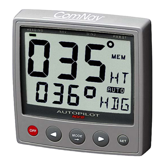
Page 33: Autopilot Instrument Control Head Operation
ComNav 1500 / 1510 Autopilot - 26 - 4. AUTOPILOT INSTRUMENT CONTROL HEAD OPERATION 4.1 Instrument Overview Page Arrow Top-Line Heading Reference Function Course/Angle AUTO Mode On Lower-Line Function Text LEFT MODE RIGHT 4.1.1 Instrument Display The display consists of two lines, a top-line with 24mm (1”) digits and a lower-line with 13mm (0.5”) digits. -
Page 34: How To Use The Push-Buttons
ComNav 1500 / 1510 Autopilot - 27 - 4.2 How to Use the Push-Buttons 4.2.1 MODE A press on MODE, moves one page to the right, indicated by the page-arrow at top of the display. In edit mode, a press on MODE moves the cursor one step to the right. -
Page 35: Setup Mode
ComNav 1500 / 1510 Autopilot - 28 - 4.2.7 Setup Mode To access Setup Mode, press and hold MODE more than 2 seconds. [Lit OFF] flashes. To move to next setup group, press MODE again. To return to standby mode, press SET when the text return 2 seconds [RET] is displayed. -
Page 36: Function
ComNav 1500 / 1510 Autopilot - 29 - 5. FUNCTION 5.1 Standby Mode At power On, the Autopilot starts in standby mode and operates as a passive compass repeater. No page-arrow is shown at the top of the display. The current course is displayed on the top-line. -
Page 37: Automatic Steering By Compass
ComNav 1500 / 1510 Autopilot - 30 - 5.2.3 Automatic Steering by Compass To select compass steering, press MODE until the page-arrow appears under HEADING, and [HDG] is flashing on the lower-line. Your present course is displayed on the top-line. This course will become the reference course the Autopilot will keep when automatic steering by compass is activated. -
Page 38: Automatic Steering By Wind
ComNav 1500 / 1510 Autopilot - 31 - Caution! The NAV function will automatically change course when the next waypoint information is displayed and the helmsman should ensure that there are no boats or other hazards on the new course as the waypoint is changing. -
Page 39: Power Steering
ComNav 1500 / 1510 Autopilot - 32 - To tack, press RIGHT and LEFT together and the boat will come about the same apparent wind angle on the opposite tack. Tack angles greater than 80° o ff the wind are not recommended due to the possibility of an accidental gibe. -
Page 40: Setup
6. SETUP 6.1 Setup Mode To get the most out of your 1500 or 1510 Autopilot, it is important to carefully setup and calibrate your Network. The settings are stored in a non-volatile memory, which means they will remain in memory after you have turned off the power. To get an overview of your Network settings, we recommend that you note your settings. -
Page 41: Lighting Setup Group [Lit]
ComNav 1500 / 1510 Autopilot - 34 - Caution! All setup routines can be adjusted while the boat is underway with Autopilot functions activated. Always be in a position to monitor the boat’s heading and to watch for navigational hazards when calibrating the Autopilot. Be prepared to turn off the Autopilot by a long press on OFF, to revert to manual steering immediately if an undesired heading occurs. -
Page 42: P2, Damping Of Compass Heading [Sea]
ComNav 1500 / 1510 Autopilot - 35 - 6.3.3 P2, Damping of compass heading [SEA] Possible settings are [0] = Minimum to [9] = Maximum. Set by the APC routine. This setting is a combination of yaw dead-band (compass sensitivity) and compass damping. The minimum setting may only be used under calm sea conditions to avoid unnecessary rudder correction due to compass acceleration errors. -
Page 43: P4, Damping Of Wind [Wse]
ComNav 1500 / 1510 Autopilot - 36 - 6.3.5 P4, Damping of wind [WSE] Possible settings are [0] = Minimum to [9] = Maximum. Default setting is [2]. Damping of wind transducer. The factory default setting should be adequate. In very heavy weather or unstable wind conditions, unnecessary corrections may be minimized by increasing the setting. -
Page 44: P8, Rudder Reduction Speed [Rrs]
ComNav 1500 / 1510 Autopilot - 37 - 6.3.9 P8, Rudder Reduction Speed [RRS] Possible settings are [0] = Minimum to [9] = Maximum. Set by the APC routine. The [RRS] controls the flow of the Pumpset. It will effect the Pumpset, but not a solenoid valve steering system. -
Page 45: Alarm Setup Group [A]
ComNav 1500 / 1510 Autopilot - 38 - 6.4 Alarm Setup Group [A] To silence an alarm, press any push button. 6.4.1 A0, Return [RET] To return to previous mode, press SET when the text [RET] is displayed. 6.4.2 A1, Pilot Course Alarm [PCA] Possible settings are [OFF] and [00°-99°]. -
Page 46: Compass Setup Group [C]
ComNav 1500 / 1510 Autopilot - 39 - 6.5 Compass Setup Group [C] Auto-deviation, auto-deviation-check and auto-deviation clear, are only available if a NX2 compass transducer is connected. The auto-deviation routine will automatically correct all possible faults, except alignment. Note! As soon as you place any kind of ferrous items close to the compass, the auto-deviation and auto-deviation check routines should be repeated. -
Page 47: C4, Check Auto-Deviation [Auto Chk]
ComNav 1500 / 1510 Autopilot - 40 - If not successful, an error messages can be displayed: • [Err 15]: Make sure an Autopilot function is not activated and carry out the auto-deviation procedure again. • [Err 16]: Auto-Deviation is not possible, because a NMEA MIN 400°... -
Page 48: C6, Adjust Compass Alignment [Adj]
ComNav 1500 / 1510 Autopilot - 41 - 6.5.7 C6, Adjust Compass Alignment [ADJ] Possible settings are [000°] to [359°]. Default setting is [000]. Compass transducer alignment correction or the so called, ”A-fault”. Allows 180° reversed mounting if needed. Never mount the transducer at right angles to the boats fore-aft line. -
Page 49: Dockside Testing
ComNav 1500 / 1510 Autopilot - 42 - 7. DOCKSIDE TESTING 7.1 Preparations Start checking the following: • Familiarize yourself with the operating procedures by reading sections Operation, Function and Setup. • Double check all wiring connections and DIP Switch settings prior to connecting power to the system. -
Page 50: Re-Initializing The Instrument
ComNav 1500 / 1510 Autopilot - 43 - Warning! Do not activate any Autopilot functions until Dockside Testing and Sea Trials APC routine have been performed. 7.2.3 Re-Initializing the Instrument If two instruments have been given the same ID number by mistake, you must re-initialize the instruments to avoid Network disturbance and blockage of data. -
Page 51: Adjust The Pumpset Flow Rate
ComNav 1500 / 1510 Autopilot - 44 - Air in the system may cause noisy Pumpset operation. When the Pumpset becomes quieter and the steering moves smoothly and the linear drive responds instantly in both directions, it may be assumed that most air is out of the system. -
Page 52: Sea Trials
ComNav 1500 / 1510 Autopilot - 45 - 8. SEA TRIALS 8.1 Preparations Take your boat out at half speed to calm seas away from other boats or obstructions to run the sea trials. Then proceed as per below. Warning! Do not activate any of the Autopilot functions (Compass, Nav or Wind) at dockside as the rudder may go hard over, since the APC routine has not been carried out yet. - Page 53 ComNav 1500 / 1510 Autopilot - 46 - If the APC fails: Error message 34 (calibration failure) is displayed. This is most likely caused by too much air still in the system. To escape the error message, press any push-button. Revert to 10.3. ”How to remove air from the system”. Note! You can ”help”...
-
Page 54: Fine Tuning
ComNav 1500 / 1510 Autopilot - 47 - 9. FINE TUNING The factory default settings and the APC routine will provide acceptable performance for most boats, but each boat has different steering characteristics and some fine tuning may be necessary for optimum performance. - Page 55 ComNav 1500 / 1510 Autopilot - 48 - To find the optimal [RUD] and [CRD] settings at different boat speeds, or when the boat is towing, follow the procedures outlined in #3 and #4 above. Make a record of the different settings needed to control the boat at all typical speeds, loads and weather conditions normally experienced.
-
Page 56: Optional Fine Tuning For Special Applications
ComNav 1500 / 1510 Autopilot - 49 - 9.1 Optional Fine Tuning for Special Applications Potentiometer adjustments, functionality on Distribution Unit. VR1: Anti-hunt control for rudder: Inappropriate adjustment could result in steering oscillations or degradation of steering performance. The potentiometer is factory set at minimum deadband setting. -
Page 57: Problem Solving
- 50 - 10. PROBLEM SOLVING 10.1 General Before you contact your ComNav dealer, and for them to give you better service, please check the following points and make a list of: • A ll connected instrument and transducers, including their software versions. - Page 58 ComNav 1500 / 1510 Autopilot - 51 - SYMPTOM CAUSE ACTION Motor Pumpset turns but the Pumpset drive section in Replace transistors, integrated rudder doesn’t move. Distribution Unit may have failed circuits or entire circuit board. to open. Broken or loose motor coupling Replace or tighten coupling as necessary.
- Page 59 ComNav 1500 / 1510 Autopilot - 52 - SYMPTOM CAUSE ACTION Rudder Angle Indicator is Rudder Transmitter is defective Replace Rudder Transmitter or displaying erratic values. (noisy). potentiometer within. Check for loose or broken wires Reconnect tightly. in terminal strips.
-
Page 60: Nx2 Network Error Messages With Cause And Remedy
To escape from an error message, press any push-button. If not possible to escape, reset power (turn off and on again), then remedy the situation as suggested below. Note! For errors marked with [*], contact your ComNav dealer or the factory in order to return the unit for rectification. MESSAGE AND CAUSE... - Page 61 ComNav 1500 / 1510 Autopilot - 54 - MESSAGE AND CAUSE REMEDY Auto-deviation failure. Error larger than 1.5°. The boat probably hit a wave during the turn. Redo. GPS to CPU communication error. Reset power. GPS acquisition failure (time out).
-
Page 62: Maintenance
ComNav 1500 / 1510 Autopilot - 55 - 11. MAINTENANCE 11.1 Instrument Maintenance • T o clean the instrument, use only mild soap solution and rinse with water. • D o not use detergents or high pressure washing equipment. -
Page 63: Technical Specifications
ComNav 1500 / 1510 Autopilot - 56 - 12. TECHNICAL SPECIFICATIONS 12.1 Autopilot Instrument Dimensions: 113mm x 113mm x 23mm (4.3” x 4.3” x 0.9”) Weight: 260g (9.17 oz) Enclosure: Water proof Instrument cable: 0.4 m (16”) Power supply: 12 V DC (10-16 V). The instrument is polarity protected. -
Page 64: Pumpsets
ComNav 1500 / 1510 Autopilot - 57 - Temperature range: The above products have the same temperature range. Storage: -30°C to +80°C ( -22°F to 176°F) Operation: -10°C to +70°C (14°F to 158°F) 12.5 Pumpsets Enclosure: Splashproof Ambient Temperature Range: -5°C to +50°C Model Max. -
Page 65: Abbreviations
- 58 - ComNav 1500 / 1510 Autopilot 13. Abbreviations Abbr. Description ADJust ALarM Automatic Pilot Calibration Automatic Trim Control Apparent Wind Angle BATtery Bearing Original Destination BeaRinG Boat SPeed Bearing To Waypoint Calibrate 10 CALibrate Course Deviation Indicator Communaute Europèenne... - Page 66 - 59 - ComNav 1500 / 1510 Autopilot metres per second Magnetic North MEMory MINimum Magnetic North Man Over Board North NAVigate Nautical Mile NMEA National Marine Electronic Association Off Course Alarm Pilot Course Alarm PoWeR Random Access Memory RETurn...
- Page 67 ComNav 1500 / 1510 Autopilot - 60 - The boat is right of the desired track Apparent wind angle from port Apparent wind angle from starboard Rudder angle port Rudder angle starboard Minus Plus...
Need help?
Do you have a question about the 1500 and is the answer not in the manual?
Questions and answers