
Related Manuals for ComNav 1420


Summary of Contents for ComNav 1420
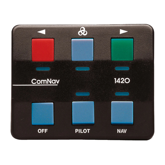
- Page 1 1420 Autopilot System Installation & Operation Manual COMPLIES WITH CE REGULATIONS PN 29010012 V1.3...
- Page 3 1420 Autopilot System Installation & Operation Manual Document PN 29010012 V1.3...
- Page 4 First Printing: January 1993 Revised: June 2000 Revised: January/February/June 2009 Document PN 29010012 V1.3...
- Page 5 ELCOME Congratulations on your purchase of a ComNav Marine 1420 Autopilot System Autopilot System! At ComNav, we are dedicated to reliability & quality in all our products, and proud of our prominence as a leader in the design and manufacture of marine autopilot systems. We promise to do our best to ensure your satisfaction with your new Autopilot System.
- Page 6 ComNav Marine 1420 Autopilot System This page is intentionally blank. Document PN 29010012 V1.3...
-
Page 7: Table Of Contents
ComNav Marine 1420 Autopilot System TABLE OF CONTENTS Product Description........................5 Before You Start..........................6 Unpacking and Identification......................... 6 Manual Conventions ............................. 6 Tools Required.............................. 7 Parts List ............................... 9 Installation Instructions ......................13 1420 Autopilot System ..........................13 Planning.............................. 13 Processor Location ........................13 Compass Location ......................... - Page 8 ComNav Marine 1420 Autopilot System Piloting with the 1420 Autopilot System.................45 Steering Control Settings ..........................45 Turning ON the Autopilot:........................45 Turning the Autopilot OFF ........................45 Determining Rudder Response Settings ....................46 Setting the Slow Speed Rudder Response..................46 Slow Speed Turns and Course Changes...................
-
Page 9: Product Description
Autopilot to steer as well as it can with the Rudder Feedback, it will The 1420 Autopilot System can steer the allow the Autopilot to be used until repairs vessel on a constant Heading, or along a can be made. -
Page 10: Before You Start
ComNav Marine 1420 Autopilot System Before You Start Manual Conventions Thank you for buying the ComNav 1420 Autopilot System. It will make boating In this manual, the names of the main safer, easier and more enjoyable for you! components are capitalized. -
Page 11: Tools Required
ComNav Marine 1420 Autopilot System Tools Required The general tools & other items you will If you purchased a 1420 with a Hydraulic need while installing the system are: Reversing Pump, a list of the tools you will require specifically for the installation Basic Tool Kit of the Reversing Pump is on page 25. - Page 12 ComNav Marine 1420 Autopilot System 1420 System Diagram Document PN 29010012 V1.3...
-
Page 13: Parts List
ComNav Marine 1420 Autopilot System Parts List Note: Parts are not drawn to any scale. Processor. PN 20070003 Control Head. PN 20070002. This part includes 25 feet (7.6 m) of cable wired to it. Control Head Mounting Clip and Spacer (these are included in the Accessory Kit). - Page 14 ComNav Marine 1420 Autopilot System ComNav Fluxgate Compass. PN 20320003. This has 40 feet (12.2 m) of cable wired to it; the other end of the cable has stripped & tinned wires. If you purchased a system with a Heading Rate...
- Page 15 • 1420 Installation & Operation Manual (this manual, PN 29010012). If you purchased a system with a ComNav hydraulic pump, one of two models, at one of two operating voltage ratings, will be included. All the pumps look very similar, so inspect the labels carefully.
- Page 16 ComNav Marine 1420 Autopilot System This page is intentionally blank. Document PN 29010012 V1.3...
-
Page 17: Installation Instructions
Processor in the Processor Location space where it is to be located. In choosing a location for your ComNav Do not mount the Processor near heat 1420 Autopilot System, remember that sources, such as heat radiators, or over the cable from the Control Head to the engines. -
Page 18: Power Connection
ComNav Marine 1420 Autopilot System Grounding Power Connection The Power Cable also contains a There is 7.5 feet (2.3 m) of power cable grounding wire. Connecting this wire to a included with your Autopilot System. We good ground (see * below) may reduce... -
Page 19: Installing The Mounting Clip And Spacer
ComNav Marine 1420 Autopilot System Fluxgate Compass Installation Installing the Mounting Clip And Spacer Fluxgate Compass The fluxgate compass must be correctly positioned or it will not work. correctly position Fluxgate Head Mounting Clip and Spacer Compass, mount it so that the top surface The Mounting Clip is used for mounting (with the cable gland) is up. -
Page 20: Rotary Rudder Feedback Installation
ComNav Marine 1420 Autopilot System Rotary Rudder Feedback Installation If you have a 1420 Autopilot System with an Outboard Feedback, please go to page 19. Select the following parts from the 1420 Autopilot package: Brass Ball Joint (Included with linkage) - Page 21 ComNav Marine 1420 Autopilot System Mounting the Rudder Feedback In the diagram above notice that: To align the Rudder Feedback Arm & the Rudder Post Arm correctly, you may need the Rudder Feedback Arm is above • to make a mounting base for the Rudder the cable entry gland Feedback.
- Page 22 ComNav Marine 1420 Autopilot System Assembling the Rudder Feedback Arm: Loosen the adjustment block that keeps Measure the approximate diameter of the two pieces of the Rudder Feedback your rudder post in inches. Linkage from sliding. The Rudder Post Arm has several holes Snap the Rudder Feedback Linkage onto drilled through it.
-
Page 23: Outboard Feedback Installation
ComNav Marine 1420 Autopilot System Outboard Feedback Installation If you have a Rotary Rudder Feedback, please go to page 16. Introduction Outboard Feedback sends The Outboard Feedback is provided with information about the rudder or propeller 30 feet (9.1 m) of cable. - Page 24 ComNav Marine 1420 Autopilot System Mounting Hardware Mount the Outboard Feedback so that it will not be damaged when the motor is tilted for trailering. Mounting Outboard Feedback Use a tape measure or ruler to position mounted with the sliding rod facing either the Outboard Feedback rod so that it left or right.
- Page 25 Tighten the nuts and the stainless steel band clamp securely. Run the cable forward to the 1420 Processor location. Choose a route for Minimum Bend Radius the cable so that the minimum bend radius in the cable is at least 4.2” (10.7 cm).
- Page 26 ComNav Marine 1420 Autopilot System Outboard Feedback Mounting to Front Mount Cylinder Document PN 29010012 V1.3...
-
Page 27: Rudder Drive
ComNav Marine 1420 Autopilot System Rudder Drive The next step is to install the Rudder Drive. • If the system you purchased includes a Reversing-Motor Hydraulic Pump, follow the instructions in this section. • If your system came with a Cable Drive, follow the Installation Instructions that came with that. -
Page 28: Pump Models & Specifications
ComNav Marine 1420 Autopilot System Pump Models & Specifications There are two models of ComNav pumps, defined by the maximum size of cylinder they can be used with: 18 in or 30 in . Each model also has a choice for the operating voltage of the pump’s motor: 12 or 24 VDC. -
Page 29: Types Of Steering Systems
ComNav Marine 1420 Autopilot System Types of Steering Systems There are two general types of steering systems: Two Line systems, and Three Line systems. The pump connection to the steering system is different for each type. There are separate instructions below for each type (see pages 28 & 29). -
Page 30: Notes & Cautions
ComNav Marine 1420 Autopilot System Notes & Cautions Before beginning to connect the pump to the steering system, review the following points: Cap or cover the ends of hoses with a clean rag before pushing them between • bulkheads. Wipe copper filings off freshly cut and reamed copper tube. Do not blow the filings off. -
Page 31: Installing The Pump
ComNav Marine 1420 Autopilot System Installing the Pump Installation of the pump consists of: • Finding a mounting location for the pump • Partially draining the steering system • Mounting and connecting the pump to the existing steering lines • Filling and bleeding the steering system A suitable mounting location for the pump MUST: •... -
Page 32: Hydraulic Connections
ComNav Marine 1420 Autopilot System Hydraulic Connections Next, make the appropriate hydraulic connections, according to whether you have a Two Line or Three Line Steering System. Hydraulic Connections for Two Line Steering Systems 2 Line Steering System Connections Delivery Lines: Ports A and B in the diagram above are the input/output ports of the pump and must be connected to the steering lines coming from the steering cylinder. - Page 33 ComNav Marine 1420 Autopilot System Hydraulic Connections for Three Line Steering Systems 3 Line Steering System Connections Delivery Lines: In the above diagram, Ports A and B are the input/output ports of the pump, and must be connected to the steering lines between the steering cylinder and the Uniflow valve.
-
Page 34: Fill And Bleed
ComNav Marine 1420 Autopilot System Fill And Bleed After you have installed your Pump, fill it with hydraulic fluid, and then bleed it. The first part if this procedure can be done right away – but for the rest, the Autopilot must be installed and powered up, so you will be referred back here during Autopilot Setup. - Page 35 ComNav Marine 1420 Autopilot System Bleeding cylinder, rod moving left Bleeding cylinder, rod moving right. Document PN 29010012 V1.3...
- Page 36 ComNav Marine 1420 Autopilot System 8. Refill your steering system from the 13. Close all bleeding screws or nipples. highest reservoir. Clean up any oil spills and wipe fittings clean. Remove any buckets 9. Adjust the bleeding screws so that...
-
Page 37: Wiring The Processor
ComNav Marine 1420 Autopilot System Wiring the Processor Place the Processor in front of you with the lettering right side up. Remove the four Phillips screws from each end. Remove the end pieces of the Processor enclosure. Looking into the open ends of the Processor you will see several green terminal strips. -
Page 38: Right Side Connections
ComNav Marine 1420 Autopilot System Right Side, Cable 1 (Control Head) to J6 Note: There is an extra wire that is not used, in the 1420 Head’s cable; the wire is yellow on the original cable, brown on the alternate cable. - Page 39 BLACK GREY DRIVE P2 N/C ** PINK DRIVE P1 N/C ** GREEN GREEN +12V +12V * If the compass reading is reversed, swap these two wires ** These wires must not be connected to non-ComNav compasses Document PN 29010012 V1.3...
-
Page 40: Left Side Connections
ComNav Marine 1420 Autopilot System Right Side, Cable 3 (Rudder Feedback) to J7 Connecting the Ground Wire Left Side Connections In the Cable 5 diagram below, the Ground Next, do the left side wiring. Remove the is the green wire. It is connected to the... - Page 41 ComNav Marine 1420 Autopilot System Left Side, Cable 4 (Pump Motor) Please see the Appendices for wiring to other types of motors, or solenoids. Left Side, Cable 5 (Power) Document PN 29010012 V1.3...
-
Page 42: Connecting The Navigation Cable
ComNav Marine 1420 Autopilot System Left Side, Optional Navigation Input Connection Connecting the Navigation Cable The optional navigation data input cable Use the diagram above to wire the may be connected at this time. Parts for navigation input. The terminal strip for this are in the Accessory Kit. -
Page 43: Mounting The Processor
ComNav Marine 1420 Autopilot System Powering Up the System Mounting the Processor Once you have completed and checked Turn on the breaker for the Autopilot or the wiring, you are ready to mount the connect the Power cable to the breaker. -
Page 44: Fuse Replacement
Autopilot needs for correct polarity. repair. To replace the fuse: 1. Turn off the power to the 1420. 1. Loosen the right side watertight glands Processor, remove the end cap. Disconnect the plugs. -
Page 45: Setting Up The Autopilot System
If the light above the Pilot Key flashes at any time during the Setup Routine, the 1420’s firmware has detected an error in the procedure, or in the system’s wiring. Refer to the Problems during the Setup Routine section, page 54. - Page 46 Come back here, when done. If you did not install a Reversing Pumpset, or you are not retro-fitting the 1420 on a vessel that already has hydraulic steering, you will not have to bleed your hydraulic system. Go to The Autopilot will beep. The light under step 9 instead.
-
Page 47: Fluxgate Compass Compensation
ComNav Marine 1420 Autopilot System Fluxgate Compass Compensation In order to complete the setup of a When measurements Fluxgate Compass, it is necessary to successful, the Autopilot will turn off. take a short trip with your boat. The Setup Routine is now completed. - Page 48 ComNav Marine 1420 Autopilot System This page is intentionally blank. Document PN 29010012 V1.3...
-
Page 49: Piloting With The 1420 Autopilot System
Fast setting. Steering Control Settings When the boat speed varies, change the The 1420 Autopilot has a wide range of Sensitivity of the Fast Speed Rudder steering control settings. There are: Response by a few steps. -
Page 50: Determining Rudder Response Settings
ComNav Marine 1420 Autopilot System ⇒ If your vessel is swinging back and Determining Rudder Response Settings forth across the Course line, like this: At this point, you will have finished adjusting your compass. Move your boat to an open area of water away from docks and other boats. -
Page 51: Slow Speed Turns And Course Changes
Slow Speed Response set properly – it’s a good time to learn how to use your 1420 Autopilot to make turns and changes in Course at Slow speed. To make a one degree Course change to Starboard, briefly press the Green key. -
Page 52: Setting The Fast Speed Rudder Response
Response ⇒ If your vessel falls away from the Course line, the Fast Speed Rudder In order that the 1420 Autopilot can steer Response Sensitivity is set too low. your boat in a straight line & make smooth turns when your boat is moving at To increase Sensitivity: “fast”... -
Page 53: The Navigation Interface
Association’s NMEA 0183 language. Below is the list of the NMEA 0183 data sentences from which the Autopilot can obtain navigation data, and the order of priority in which the 1420 can use these sentences: 1. RMB + RMC 2. RMB + RMA 3. -
Page 54: Using The Navigation Interface
Course line, or that the line is to the left of the boat. Turn the Autopilot System on & Press Because of this, the 1420 Autopilot lets the Nav Key. you change the way it interprets the Watch the Control Head. -
Page 55: Operation Commands
ComNav Marine 1420 Autopilot System Operation Commands COMMAND ACTION RESULT Steer by Compass Point bow onto desired Course Boat will settle on Course Press Pilot Key Course Change: Press Red Key once Course change to Port small, to Port for every degree of desired... - Page 56 ComNav Marine 1420 Autopilot System Operation Commands (continued) COMMAND ACTION RESULT Dodge: Press and hold Red Key Vessel turns to Port to Port Rate of turn: – Same as large Course change to Port (see above) Dodge: Press and hold Green Key...
-
Page 57: Adjustment Commands
ComNav Marine 1420 Autopilot System Adjustment Commands COMMAND ACTION RESULT Rudder Response Press and hold Speed Key The Autopilot will not react Sensitivity: & then press Red Key once as strongly to course decrease deviations. It may "settle for each step of reduction in down"... -
Page 58: Problem Solving
Problem Solving Problems during the Setup Routine If the 1420 Autopilot finds a problem during the Setup Routine, the Pilot Key light will flash repeatedly. The problems which the Autopilot can detect during the various steps of the Setup Routine are listed below. -
Page 59: Problems During Normal Operation
ComNav Marine 1420 Autopilot System Problems during Normal Operation When the 1420 Autopilot detects a problem it will flash the lights on the Control Head. Note: it is not possible for the Autopilot to warn you of every potentially serious problem which can occur. - Page 60 ComNav Marine 1420 Autopilot System HEAD INDICATION PROBLEM & HOW TO FIX The lights are all blinking and The Processor has overheated. the Autopilot is no longer moving CHECK: the rudder or the outboard. • Is there a short circuit in the connection to the Reversing Pump? •...
- Page 61 ComNav Marine 1420 Autopilot System HEAD INDICATION PROBLEM & HOW TO FIX The Autopilot will not switch to The Autopilot is not receiving any useful navigation data Nav function. from the navigation device. CHECK: • That the navigation device is turned on.
-
Page 62: Problems During Turn On
3. The Off Key is stuck – Try to free the Off Key. 4. The Autopilot hardware or firmware is faulty – Call your ComNav Marine Dealer for service. The lights are blinking Either of the Red Key, Green Key or Nav Key has stuck. -
Page 63: Connections To 4 And 5 Wire Motors
ComNav Marine 1420 Autopilot System Appendix A Connections to 4 and 5 Wire Motors Document PN 29010012 V1.3... -
Page 64: Connections To 4 And 5 Wire Motors (Using A Clutch Or Lockup Valve)
ComNav Marine 1420 Autopilot System Appendix B Connections to 4 and 5 Wire Motors (using a clutch or lockup valve) Document PN 29010012 V1.3... -
Page 65: Connections To Solenoid Valves
ComNav Marine 1420 Autopilot System Appendix C Connections to Solenoid Valves Document PN 29010012 V1.3... -
Page 66: Connecting A Second Station
ComNav Marine 1420 Autopilot System Appendix D Connecting a Second Station R E D B L A C K O R B R O W N G R E E N B L U E W H I T E O R O R A N G E... - Page 67 Turning the Autopilot Off from the Main or Second Station At the Head which is the active one, press and hold the Off key. Note that the 1420 cannot be turned off from a Control Head which is not the active one.
-
Page 68: Connecting The Nmea 0183 Heading Output
Connecting the NMEA 0183 Heading Output Location of terminal strip J5 The 1420 Autopilot has a data bus that sends out NMEA 0183 heading information to other external devices such as Radars. Heading data is transmitted once per second and provides two NMEA sentences: HDM (magnetic heading) and HDG (magnetic heading, deviation &... -
Page 69: Connecting A Rudder Angle Indicator
ComNav Marine 1420 Autopilot System Appendix F Connecting a Rudder Angle Indicator SIGNAL RETURN Right-Side, Optional RAI Connection The cable gland for a Rudder Angle Indicator is in your Accessory Kit. We do not supply a cable for this installation. - Page 70 ComNav Marine 1420 Autopilot System This page is intentionally blank. Document PN 29010012 V1.3...
-
Page 71: Warranty
ComNav Dealer, and such installation has been inspected by an Authorized ComNav Dealer; the Limited Warranty Registration Card has been returned to ComNav within 14 days of the date of purchase of the Equipment by the Purchaser with Part I thereof having been completed by the Purchaser, and with the Extended Limited Warranty Card having been completed and signed by an authorized ComNav Dealer and returned to ComNav within 14 days of that inspection;... - Page 72 ComNav within 10 days of the date upon which the defect first became known to the Purchaser. Notices sent by mail will be deemed to be received by ComNav on the seventh (7th) day first following the date of posting in North America and on the tenth (10th ) day next following the date of posting anywhere else in the world.
- Page 73 Purchaser; No refund of the purchase price for the Equipment will be made to the Purchaser unless ComNav is unable to remedy the defect after having a reasonable number of opportunities to do so. Prior to...
- Page 74 PURCHASER MAY ALSO HAVE OTHERS WHICH VARY FROM STATE/JURISDICTION TO STATE/JURISDICTION. This Agreement is a legal contract between you (the “Purchaser”) and ComNav. By retaining the Equipment for more than thirty (30) days and/or installing and/or using the Equipment, the Purchaser agrees to be bound by the terms of this Agreement.
-
Page 75: Ce Compliance
ComNav Marine 1420 Autopilot System CE COMPLIANCE This product is in compliance with the Electro-Magnetic Compatibility (EMC) standards of the European Community, and bears the CE mark. It was tested according to the applicable sections contained in: CE Directives IEC 945:1994, BS EN 60945:1996... - Page 76 ComNav Marine 1420 Autopilot System OTES You can use this table to record the serial numbers of the components of your system, setup settings, any notes you made during installation, and any other information you might want to keep handy.
Need help?
Do you have a question about the 1420 and is the answer not in the manual?
Questions and answers