
Related Manuals for ComNav 1001


Summary of Contents for ComNav 1001
- Page 1 Installation & Operation Manual ComNav 1001 Autopilot COMPLIES WITH CE REGULATIONS P/N 29010007...
- Page 3 WARRANTY NOTICE Prior to the installation and/or operation of the Equipment, ensure that you read, understand and accept the conditions of the warranties as detailed on the following pages. OPERATORS WARNING This Autopilot will automatically steer your vessel however, it is only an aid to navigation.
-
Page 4: Table Of Contents
TABLE OF CONTENTS 1001 AUTOPILOT SYSTEM DRAWING _________________________________________ 3 BASIC OPERATION __________________________________________________________ 3 AUTOPILOT _____________________________________________________________________ 4 REMOTE CONTROL _____________________________________________________________ 6 INTRODUCTION ____________________________________________________________ 7 SPECIFICATIONS ___________________________________________________________ 8 1001 AUTOPILOT INTERCONNECTION DIAGRAM ______________________________ 9 OPTIONAL DRIVE SYSTEMS ________________________________________________ 11 INSTALLATION INSTRUCTIONS _____________________________________________ 12... - Page 5 PILOT _________________________________________________________________________ 44 NAV ___________________________________________________________________________ 47 REMOTE CONTROLS ___________________________________________________________ 48 REMOTE CONTROLS _______________________________________________________ 50 COMNAV 101 REMOTE CONTROL _______________________________________________ 50 COMNAV 201 REMOTE CONTROL _______________________________________________ 53 COMNAV 211 REMOTE CONTROL _______________________________________________ 54 ERROR CHECKING _________________________________________________________ 55 PROBLEM SOLVING ____________________________________________________________ 59...
-
Page 6: 1001 Autopilot System Drawing
1001 AUTOPILOT SYSTEM DRAWING... -
Page 7: Basic Operation
BASIC OPERATION AUTOPILOT 2. TO POWER STEER THE VESSEL\ 1. TO INITIALIZE THE AUTOPILOT\ POWER STEER MODE STANDBY MODE To turn the rudder to port and to Turn the master select switch to starboard, turn the master select switch to the STANDBY position. - Page 8 CHANGE VESSEL'S 6. TO INTERFACE WITH A COURSE: NAVIGATION COMPUTER \NAV MODE Start navigating towards To obtain the desired course, selected route or waypoint, using a leave the master select switch in the Navigation Computer which has an PILOT position. Estimate the number of NMEA 0183 output.
-
Page 9: Remote Control
If the unit that will take control is not in the same mode as the unit 2. TO USE THE COMNAV 1101 currently in control, a sudden SECOND STATION: course change could occur. -
Page 10: Introduction
INTRODUCTION This autopilot microprocessor The autopilot is equipped to interface with operated (Proportional-Integral- a GPS, Loran C, or any other navigation Differential) controller, working from either computer which outputs one of the NMEA high quality, externally gimballed 0183 formats at 4800 Baud. magnetic ships steering compass fitted with a fluxgate sensor or a direct earth’s The autopilot is designed to accept one... -
Page 11: Specifications
SPECIFICATIONS Operating Voltage: 10 VDC TO 30 VDC For Use With 12 or 24 VDC Battery Systems only Operating Current: 0.18 Amps (minimum) -15 To +60 °C Operating Temperature Range: Heading Resolution: 0.25 Degree Heading Accuracy: + 2.0 Degrees Course Set Resolution: 1.0 Degree PORT/STBD Output Type: Open Collector, 3 Amps Max... -
Page 12: 1001 Autopilot Interconnection Diagram
1001 AUTOPILOT INTERCONNECTION DIAGRAM... - Page 13 DRIVE SYSTEM OPTOINS...
-
Page 14: Optional Drive Systems
OPTIONAL DRIVE SYSTEMS commercial pleasure - CPUFC Flow Control Uniblock vessels over 50 ft where heavy usage 12, 24 or 32 VDC will be the norm (hydraulic steering): - CPUTS & CT5 - Two Speed Uniblock 12, 24 or 32 VDC - Belt Driven Pump - Direct Driven Pump For vessels with hydraulic cylinder... -
Page 15: Installation Instructions
INSTALLATION INSTRUCTIONS AUTOPILOT The autopilot is normally mounted in the Position the cutting template on vessel's wheelhouse. It can also be the panel where the autopilot is to be mounted in a more exposed location, mounted, and mark the opening onto the such as the flying bridge of a sports panel. -
Page 16: Compass
COMPASS FOR COMNAV FLUX-GATE COMPASS FOR OTHER FLUXGATE COMPASSES The compass MUST be mounted as close as practical to the vessels centre The autopilot can be used with a of pitch and roll. This is typically low in the Fluxgate Compass which outputs DC... - Page 17 CONNECTION FOR NON-1001 FLUXGATE COMPASSES PLUG PIN 1001 COMNAV NON-COMNAV NUMBERS FLUXGATE FUNCTION CONNECTIONS BLUE COSINE COSINE * DRIVE P1 BLACK DRIVE P2 SHIELD GROUND GROUND WHITE REFERENCE REFERENCE YELLOW SINE SINE * GREEN +12V +12V * If the reading is reversed, swap these two wires.
- Page 18 This is particularly important in high latitudes, (such as Alaska, Labrador or the North Sea), where the horizontal component of the earth's magnetic field (which is the portion the compass is trying to detect) is very small relative to the magnetic field of the vessel.
- Page 19 IMPORTANT It is important to remember that the compass is a vital part of the autopilot system. Locating it properly, particularly on steel hulled vessels, is essential to ensure proper operation of the autopilot. We recommend that the services of a qualified compass adjuster be used to select the best installation location and to compensate the compass properly for deviation, including that caused by heeling error.
- Page 20 Your dealer can supply a compass Rotate compass through specifically designed for the ComNav degrees, comparing readings every 20 1001 autopilot. degrees. The readings should agree within +/- 2 degrees (4 degrees total error) if the compass is compatible with...
-
Page 21: Distribution Box
To ensure a neat appearance, the reversing electric drive unit manufactured cover has only had the minimum number by ComNav Marine will not exceed 30 of openings prepared in advance. amps. The suggested types and gauges of 3. - Page 22 Drive Boxes manufactured without damaging the autopilot. A pair of ComNav Marine as a reference for diagnostic LED's, one red and one green, are provided in the distribution box to SPEED CONTROL (terminal 7). confirm the correct operation of these two outputs.
- Page 23 19. RAI SIGNAL 20. RAI RETURN These two terminals are used to run up to three ComNav Marine rudder angle indicators. Multiple rudder angle indicator installations must be wired in series. If all the indicators move to port when the rudder is moving to starboard, reverse the connections to these terminals.
-
Page 24: Rudder Follower
RUDDER FOLLOWER The rudder follower is used to transmit the position of the rudder back to the autopilot. It should be connected to whatever part of the steering system the autopilot controls. Normally, this will be the vessel's rudder. However, if the vessel has 2 stage steering, such as Wagner M10, Kobelt Power Steering or a similar system where the autopilot drives... - Page 25 With either rudder follower. If the length of cable supplied is too short The distance between the centerline of to reach all the way to the distribution box, the rudder post and the rudder follower obtain a terminal strip and sufficient must not exceed 24 inches.
- Page 26 Figure 6 - Rudder Feedback correctly installed to rudder post...
-
Page 27: Navigation Interface
Nav Device sequences to the formats available from its data sheets. next waypoint. This is the best type of The 1001 autopilot will only support Heading To Steer information, as it NMEA 0183 data format and therefore prevents the wandering which may occur that format must be selected. - Page 28 The variations of NMEA 0183 which are currently supported by the autopilot along with the information the autopilot uses from that sentence are listed below: Loran C Navigation Information - Receiver Status plus Vessel Speed plus Variation GPS Navigation Information – Receiver Status plus Vessel Speed plus Variation The RMA or RMC data sentence is always combined with the RMB data sentence.
-
Page 29: Cross Track Error Response
following: Vessel Speed relative to water from Dual Doppler Speed Log. Vessel Heading and Water Speed Vessel Track and Ground Speed CROSS TRACK ERROR RESPONSE The response of the autopilot is set with However, some manufacturers have used the master select switch in the NAV the (L)eft indicator to mean that the position. -
Page 30: Checksum Evaluation
'cn:OF' is displayed. **** IMPORTANT **** If you have installed a ComNav Marine reversing motor pump, a constant running pump or an engine driven pump, there are several checks that must be done during the first several weeks of usage in order to prevent poor or dangerous steering performance. During this period you must check for air or leaks in your hydraulic system. -
Page 31: Dockside Set-Up
DOCKSIDE SET-UP INTRODUCTION It is essential that the DOCKSIDE SET- The goals of the dockside set-up are: UP procedure be performed before taking To set the limits of the rudder the vessel out on the water. travel. This procedure will be much easier to do To adjust the R.A.I. -
Page 32: Adjust Rudder Angle Indicator (If Installed)
The autopilot will turn on the starboard Please note that no vessel will steer output for 2 seconds. If the rudder moved properly, especially in rough weather, to port, the autopilot will sound its alarm with an H.O. Time over 28 seconds. and flash the word 'Stbd' on the display. -
Page 33: Configuring The Compass
Nav Device. If the interface still cannot be made to Press the TURN key once to see which work, contact your dealer or ComNav type of data the autopilot is using to verify Marine directly for assistance. -
Page 34: Sea Trials
SEA TRIALS The purpose of sea trials is to swing the compass, (CPS2 or CPS3) if it is a fluxgate compass, and to check the general operation of the autopilot. CAUTION: A potentially dangerous situation can be caused by the addition or movement of magnets in the vicinity of the compass. - Page 35 5 seconds, which Press the ADJUST key. The display will should now be correct. switch to 'C.AdJ'. If the autopilot is using a ComNav Press either the up or down ARROW key Fluxgate compass, the final adjustment to bypass the compass adjustment is the heeling adjustment.
- Page 36 so the display reads 'SLOW'. Press the ADJUST key once. If the display reads 'SLOW', press either the up Make several 40 degree course changes or down ARROW key once so the display and use the instructions in the "FAST" reads 'FASt'.
- Page 37 If the autopilot is using a ComNav If the autopilot is using a different Fluxgate Compass, try changing the brand of fluxgate compass, or a heeling adjustment to reduce or eliminate magnetic compass with fluxgate the problem. sensor, a qualified compass adjuster will...
-
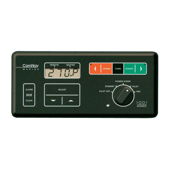
Page 39: Controls
CONTROLS The controls consist of a five position master select switch, and a 9 position membrane keypad. The controls operate as follows: MASTER SELECT SWITCH POWER STEER All power to the autopilot is turned off. The display will be blank. STANDBY The left three digits of the display... -
Page 40: Membrane Keypad
The ADJUST key can now be used to PILOT change the Rudder, Counter Rudder, Yaw and Turn Rate settings. The vessel will steer the course indicated on the left three digits of the display. The course the vessel is steering can be Place the master select switch in this changed by pressing either the red or position when the autopilot is being... - Page 41 correction applied in half. DODGE KEYS Pressing either the red or green DODGE key will dodge the vessel in that direction. Controls the amount of deviation from The display will switch to show the the programmed course the autopilot vessel's rudder angle. Pressing and will allow before...
- Page 42 TABLE V: SETTING TURN RATE 0.5 DEG/SEC 1.0 DEG/SEC 1.5 DEG/SEC 2.0 DEG/SEC 2.5 DEG/SEC 3.0 DEG/SEC 3.5 DEG/SEC 4.0 DEG/SEC 4.5 DEG/SEC 5.0 DEG/SEC...
-
Page 43: Special Turns
SPECIAL TURNS When the autopilot is in the PILOT mode, pressing the TURN key followed by either the red or green ARROW key initiates the PRE-SELECTED type of special turn. EMERGENCY TURN pressing the TURN key followed by the red ARROW key. The autopilot will make The Emergency Turn is selected by a 90-degree turn to port. -
Page 44: U Turn
U TURN The U-Turn is selected by placing the autopilot STANDBY mode, pressing the TURN key, followed by either the red or green ARROW key until the display shows 'U.trn'. This turn is also just what it sounds like, a 180 degree turn. -
Page 45: Operation
OPERATION To tell if you have the most current For one second the first thing you will see version of the autopilot program, call the when the autopilot is turned on is the factory with the software revision number software revision number. Example: displayed. -
Page 46: Power Steer
NAVIGATION INTERFACE section this manual more information. To display the battery voltage supplied to To change the type of special turn the autopilot, press the ADJUST key four (Emergency turn, Continuous turn, or U- times. turn) that will occur when you select a special turn in the PILOT operating mode, press the TURN key followed by either the red or green ARROW key. -
Page 47: Pilot
Rudder Travel can be measured using an analog Rudder Angle Indicator (if one is fitted), or by measuring the stroke of the To set the hard-over to hard-over Rudder hydraulic cylinder (Cylinder Stroke) and Travel, press the ADJUST key twice. the distance from the center of the rudder post to the point on the tiller where the This is used to more accurately calibrate... - Page 48 TO CHANGE THE VESSEL'S COURSE THE SPEED SENSITIVITY IS TURNED BY ONE DEGREE, press and release the OFF by either manually switching the red or green ARROW key. autopilot from SLOW to FAST, from FAST to SLOW, or by rotating the master MAKE LARGER COURSE...
- Page 49 If the autopilot is using a Magnetic factory settings Rudder, Compass, problems could be caused by Counter Rudder, Yaw and Turn Rate the compass not having been swung by a are 3, 3, 1 and 6 respectively. qualified compass adjuster; the card may be sticking because of a worn pivot;...
-
Page 50: Nav
Cross Track Error as with the factory service personnel to indicated by the Nav Device to a obtain special software. The 1001 minimum. If you are in any doubt as to autopilot software only supports NMEA whether things are working correctly, 0183 format. -
Page 51: Remote Controls
REMOTE CONTROLS To use the remote control, leave the If you have mechanical steering, you can autopilot in the PILOT mode when you go disengage the clutch on the drive unit and up to the flying bridge. This will leave the return to hand steering by selecting the vessel under control. - Page 52 This page is meant to be blank.
-
Page 53: Remote Controls
REMOTE CONTROLS COMNAV 101 REMOTE CONTROL This remote control plugs into the remote PILOT position. The autopilot is now receptacle on the rear of the autopilot. steering the vessel on its current heading. Control is taken at the remote by pressing both its pushbuttons for one second. - Page 54 To change the vessel's course by one The back of the remote provides two degree, press and release either the red key-hole slots which can be used to or green pushbutton. either temporarily deposit permanently mount it on any suitable To change the vessel’s course by 10 location.
- Page 55 Table VI - 101 REMOTE Cable Connections Wire Colour Terminal Number Plug Pin Number Shield Pink White Brown Violet Grey Green Yellow Black Blue...
-
Page 56: Comnav 201 Remote Control
Control is taken at the remote by pressing both its pushbuttons for one second. The decimal point on the 1001 Control Head display will move to the REMOTE position. The Standby mode is a safety... -
Page 57: Comnav 211 Remote Control
Control is taken at the remote by pressing both its pushbuttons for one second. The decimal point on the 1001 Control Head display will move to the REMOTE position and the decimal point on the 211 Remote display will move to REM.1. -
Page 58: Error Checking
ERROR CHECKING THE AUTOPILOT WILL DISPLAY AN ERROR MESSAGE AND SOUND THE ALARM WHEN ANY OF THE FOLLOWING CONDITIONS EXIST: The checksum in one of the RMA, RMB or RMC data sentences is set incorrectly or there is a transmission problem between the navigation device and the autopilot. - Page 59 One or more of the keys on the front panel are stuck in the closed position or a remote may have a faulty pushbutton. FRONT PANEL The autopilot or remote can be used by pressing ALARM ERROR CLEAR, however, some functions may not work properly. If the test of the permanent memory indicated that one or more of the bytes of data stored were not correct, a number of controls are reset...
- Page 60 The autopilot has detected that its input voltage has dropped under 10 VDC. Check for proper alternator operation, batteries low on water, or some other condition that has caused the input voltage to drop. POWER ERROR The computer is not receiving any data from the compass.
- Page 61 The portion of RAM memory used for temporary data storage tested faulty. MEMORY The autopilot is not operable. ERROR The autopilot has detected a problem with the rudder follower. Check for broken, disconnected or shorted wires, or a defective rudder follower. The autopilot will switch to using the Ghost Rudder RUDDER program to control the rudder when the master select switch is in FOLLOWER ERROR...
-
Page 62: Problem Solving
PROBLEM SOLVING Several different problems and possible solutions are outlined below. If the recommended solution does not solve the problem, return the autopilot to an authorized service centre. AUTOPILOT DOES Check for power reaching the distribution box. NOT TURN ON. Check the main fuse or breaker panel. - Page 63 THE AUTOPILOT TURNS Check for full output voltage on the SWITCHED PWR line ON, BUT DOES NOT TURN with autopilot in the POWER STEER mode. The yellow SWI THE RUDDER. (continued POWER LED in the distribution box should come on when from page 56) the master select switch on the autopilot is in the POWER STEER or higher mode.
- Page 64 Watch the card on the autopilot compass to make sure that THE AUTOPILOT STEERS it follows the vessel’s movements properly. If the card POORLY seems to turn with the vessel for a few degrees, and then COURSES. come free, either the pivot or jewel in the compass may be defective.
-
Page 65: Ce Compliance
Annex A, Section A.4: Immunity to earth lead coupling Annex A, Section A.5: Immunity to conducted radio frequencies Annex A, Section A.6: Immunity to radiated interference Test results and a declaration of conformity are on file at the ComNav plant; ComNav Marine Ltd #15 - 13511 Crestwood Place... - Page 66 Authorized ComNav Dealer; and the Limited Warranty Registration Card has been returned to ComNav within 14 days of the date of purchase of the Equipment by the Purchaser with Part I thereof having been completed by the Purchaser, and with the Extended Limited Warranty Card having been completed and signed by an authorized ComNav Dealer and returned to ComNav within 14 days of that inspection;...
- Page 67 Purchaser. Notices sent by mail will be deemed to be received by ComNav on the seventh (7th) day first following the date of posting in North America and on the tenth (10th) day next following the date of posting anywhere else in the world.
- Page 68 HAVE OTHERS WHICH VARY FROM STATE/JURISDICTION TO STATE/JURISDICTION. This Agreement is a legal contract between you (the "Purchaser") and ComNav. By retaining the Equipment for more than thirty (30) days and/or installing and/or using the Equipment, the Purchaser agrees to be bound by the terms of this Agreement.
- Page 69 CANADA V6V 2G1 TELEPHONE: 604-207-1600 FACSIMILE: 604-207-8008 E-MAIL: sales@comnav.com WEB SITE: www.comnavmarine.com TOLL FREE IN CANADA OR THE USA; PHONE: 1-800-428-0212 FAX: 1-800-470-9611 THE 1001 AUTOPILOT SYSTEM COMPLIES WITH ALL RELEVANT CE REGULATIONS FIRST PRINTING DECEMBER 1990 REVISED December 1998...
- Page 70 PAGES 5, 6 & 7 - NEW WARRANTY POLICY December 14, 1998 Converted to Word. Removed all 1001M information & W/F references April 28, 1999 Removed all old drawing and replaced with new KVH Gyro Trac drawing. August 29, 2000 Change ComNav's address.
Need help?
Do you have a question about the 1001 and is the answer not in the manual?
Questions and answers