Table of Contents
Advertisement
Advertisement
Table of Contents

Related Manuals for ComNav 2001


Summary of Contents for ComNav 2001
- Page 1 INSTALLATION AND OPERATION MANUAL 2001 AUTOPILOT...
- Page 2 ComNav 2001 Autopilot System WARRANTY NOTICE Prior to the installation and/or operation of the Equipment, ensure that you read, understand and accept the conditions of the warranties as detailed on the following pages. OPERATORS WARNING This Autopilot will automatically steer your vessel however, it is only an aid to navigation.
- Page 3 ComNav 2001 Autopilot System Figure 1 - 2001 SYSTEM LAYOUT - 3 - P/N 29010017 V1.0...
-
Page 4: Basic Operation
ComNav 2001 Autopilot System BASIC OPERATION AUTOPILOT shows the desired course. Press the U-TURN key together with either the red or green ARROW 1. TO INITIALIZE THE AUTOPILOT: key for 1 second to start a special turn (U-Turn, Emergency Turn, or Continuous Turn) in that Turn the master select switch to the STANDBY direction. - Page 5 4. TO TAKE CONTROL AT THE AUTOPILOT FRONT PANEL: 1. TO USE THE COMNAV 101 REMOTE CONTROL: Take control at the autopilot front panel by pressing both the red and green ARROW keys Take control at the Remote by pressing both its on the autopilot front panel for one second.
- Page 6 Authorized ComNav Dealer; and the Limited Warranty Registration Card has been returned to ComNav within 14 days of the date of purchase of the Equipment by the Purchaser with Part I thereof having been completed by the Purchaser, and with the Extended Limited Warranty Card having been completed and signed by an authorized ComNav Dealer and returned to ComNav within 14 days of that inspection;...
- Page 7 . The Limited Warranty and the Extended Limited Warranty will not apply with respect to any defective Equipment unless written notice of such defect is given to ComNav, by mail to the address for ComNav set forth above, or by facsimile to ComNav at 1-604-207-8008, and is received by ComNav within ten (10) days of the date upon which the defect first became known to the Purchaser.
- Page 8 OTHERS WHICH VARY FROM STATE/JURISDICTION TO STATE/JURISDICTION. This Agreement is a legal contract between you (the "Purchaser") and ComNav. By retaining the Equipment for more than thirty (30) days and/or installing and/or using the Equipment, the Purchaser agrees to be bound by the terms of this Agreement. If the Purchaser does not agree to be bound by the terms of this Agreement, the Purchaser may return the Equipment in the same condition in which it was received for a full refund (less shipping and handling costs) within thirty (30) days of purchase.
- Page 9 ComNav 2001 Autopilot System MANUAL PUBLISHED BY: COMNAV MARINE LTD #15 – 13511 Crestwood Place RICHMOND, BC V6V 2G1 CANADA TELEPHONE: (604) 207-1600 FACSIMILE: (604) 207-8008 E-MAIL: sales@comnavmarine.com WEB SITE: www.comnavmarine.com TOLL FREE IN CANADA OR THE U.S.A. TELEPHONE: 1-800-428-0212...
-
Page 10: Table Of Contents
ComNav 2001 Autopilot System TABLE OF CONTENTS BASIC OPERATION..................................3 AUTOPILOT ................................... 3 REMOTE CONTROLS ..............................4 LIMITED WARRANTY ................................5 INTRODUCTION ..................................9 SPECIFICATIONS ..................................10 INSTALLATION INSTRUCTIONS ............................13 AUTOPILOT .................................. 13 COMPASS ..................................14 DISTRIBUTION BOX ..............................16 RUDDER FOLLOWER .............................. -
Page 11: Remote Controls
ComNav 2001 Autopilot System INTRODUCTION This autopilot is a microprocessor operated PID The autopilot is designed to accept up to two (Proportional/Integral/Differential) controller, remote controls. Control can be taken at either working from a high quality, externally gimballed remote simply by pressing both its pushbuttons magnetic ships steering compass fitted with a simultaneously for one second. -
Page 12: Specifications
ComNav 2001 Autopilot System SPECIFICATIONS OPERATING VOLTAGE: 10 VDC TO 40 VDC POWER CONSUMPTION: 6 WATTS OPERATING TEMPERATURE RANGE: -15 TO +60 DEGREES CENTIGRADE OUTPUT TYPE: OPEN COLLECTOR TRANSISTOR 3 AMPS MAXIMUM HEADING RESOLUTION: 1/2 DEGREE ON MAGNETIC COMPASS 1/2 DEGREE ON 1X GYROCOMPASS... - Page 13 ComNav 2001 Autopilot System Figure 2 - 2001 AUTOPILOT INTERCONNECTION DIAGRAM IMPORTANT – DISTRIBUTION BOX TERMAIL #9 IS A REFERENCE ONLY, IT IS NOT NEGATIVE POWER - 13- P/N 29010017 V1.0...
- Page 14 ComNav 2001 Autopilot System Figure 3 IMPORTANT – DISTRIBUTION BOX TERMINAL #9 IS A REFERENCE ONLY, IT IS NOT NEGATIVE POWER - 14- P/N 29010017 V1.0...
-
Page 15: Installation Instructions
ComNav 2001 Autopilot System INSTALLATION INSTRUCTIONS AUTOPILOT The autopilot is normally mounted in the vessel's Unscrew the two large screws from the rear of the wheelhouse. It can also be mounted in a more autopilot and remove the rear cover. Peel the... -
Page 16: Compass
ComNav 2001 Autopilot System COMPASS Locate and mount the compass in a position which minimizes magnetic interference. It should MOUNTING THE SENSOR TO NON- be at least three feet away from such equipment STANDARD COMPASSES as radios, radars, depth sounders, and engine instruments. - Page 17 Your dealer can supply a compass specifically designed for the ComNav 2001 autopilot. - 17- P/N 29010017 V1.0...
-
Page 18: Distribution Box
ComNav autopilot and confirm the correct operation of these two reversing motor drive unit will not exceed 25 outputs. amps. The only exception would be when a CT2- 40A drive unit is used. - Page 19 Control Boxes with no power applied to the indicator). The total manufactured by ComNav Marine Ltd as a current drain may not exceed +/- 2.0 milliamps. reference for SPEED CONTROL (terminal 7). A yellow LED is provided in the distribution box to...
- Page 20 24. +5V 25. COMMON (REFERENCE ONLY) These terminals are used for transmitting data out of the autopilot to either, a ComNav Remote Heading Display, a satnav, or other type of navigation computer. The function of these terminals is determined by...
-
Page 21: Rudder Follower
ComNav 2001 Autopilot System INSTALLATION INSTRUCTIONS RUDDER FOLLOWER The rudder follower is used to transmit the position of the rudder back to the autopilot. It should be connected to whatever part of the steering system the autopilot controls. Normally, this will be the vessels rudder. - Page 22 ComNav 2001 Autopilot System If the length of cable supplied is too short to reach With either rudder follower: all the way to the distribution box, obtain a terminal strip and sufficient additional cable from your dealer. Mount the terminal strip in a The distance between the centerline of the rudder convenient DRY location.
- Page 23 ComNav 2001 Autopilot System Figure 5 - Rudder Feedback correctly installed to rudder post - 23- P/N 29010017 V1.0...
-
Page 24: Remote Controls
ComNav 2001 Autopilot System INSTALLATION INSTRUCTIONS REMOTE CONTROLS Either optional remote control can be hand-held If a type 101 remote control is plugged into the or permanently mounted. To mount the remote REMOTE 1 receptacle, Dip Switch 5 should be control permanently, drill two holes through the OFF (or OPEN). -
Page 25: Remote Heading Displays
ComNav 2001 Autopilot System INSTALLATION INSTRUCTIONS REMOTE HEADING DISPLAYS Up to four optional Remote Heading Displays Refer to the wiring diagram supplied with the can be run by the autopilot. These can be Remote Heading Display to connect the cable mounted anywhere convenient using the supplied into the autopilot distribution box. -
Page 26: Navigation Interface
ComNav 2001 Autopilot System NAVIGATION INTERFACE NMEA 0182 If the autopilot is being interfaced to a navigation device with any of the NMEA 0180, 0182, or 0183 outputs, determine the type(s) of output If the autopilot is using NMEA 0182 data to format(s) from its data sheets. - Page 27 ComNav 2001 Autopilot System The standard baud rate for the 0183 data format is the three letter sentence identifier, so it will 4800 baud. receive information from any Nav. Device which transmits the correct data sentences. This data format was developed to allow a...
- Page 28 ComNav 2001 Autopilot System VTG - Vessel Track and Ground Speed NAVIGATION INTERFACE CROSS TRACK ERROR RESPONSE The response of the autopilot is set with the Some manufacturers, however, have reversed master select switch in the NAV position. their cross track error identification. Because of...
-
Page 29: Data Output
Dip Switch 4 to OFF. The Remote Heading Display format is for use The BCD format is a three wire signal. One with ComNav Marine Remote Heading Display wire connects to TX CLOCK, terminal 22 in the repeaters. autopilot distribution box. This terminal transmits a synchronizing clock signal. - Page 30 ComNav 2001 Autopilot System The NMEA 0183 data format is becoming the The signal is 5 volts in amplitude, and transmitted standard for communication between marine at 4800 baud. The output has enough drive to electronic devices. A factory modification is transmit to 2 standard NMEA 0183 'listeners', ie.
-
Page 31: Dip Switches
ComNav 2001 Autopilot System DIP SWITCHES The Dip Switches are used to control a number of autopilot functions. The function of the each Dip Switch is summarized in the following table: Table III - DIP SWITCH FUNCTIONS DIP SWITCH FUNCTIONS... -
Page 32: Dockside Set-Up
ComNav 2001 Autopilot System DOCKSIDE SET-UP INTRODUCTION It is essential that the DOCKSIDE SETUP The goals of the dockside set-up are: procedure be performed before taking the vessel out on the water. To set the limits of the rudder travel. - Page 33 ComNav 2001 Autopilot System DOCKSIDE SET-UP ADJUST RUDDER ANGLE INDICATOR (if installed) Turn MASTER SELECT switch to Turn the wheel hard over. Turn the RAI STBY mode. Turn the wheel by hand. ADJUST so that the indicators show See if the rudder angle indicators show hard over correctly.
- Page 34 ComNav 2001 Autopilot System If the starboard (green) key comes on IF YOU CANNOT MAKE THE RUDDER after the port key goes off, the RETURN SMOOTHLY TO IT'S POSITION: PREDICTOR MAGNITUDE is set too low. Turn it clockwise a 1/4 turn.
- Page 35 NMEA 0180 information to your autopilot. It indicates that your Contact your dealer or ComNav Marine for wiring connections are correct. assistance if the problem persists. Please have available your pilot serial number and the make and model of your Nav device.
-
Page 36: Sea Trials
ComNav 2001 Autopilot System SEA TRIALS 1. Adjust the external controls to the following COUNTER RUDDER setting increased only 1 initial settings: position to '7' as the weather declines. RUDDER As the vessel's speed decreases, the rudder COUNTER RUDDER becomes less effective. In general, the RUDDER... - Page 37 ComNav 2001 Autopilot System heeling error (particularly on steel hulled vessels), for best operation. Adjustments of this sort should NOTE: only be performed by a qualified compass A potentially dangerous situation is adjuster. caused by addition or movement of any...
-
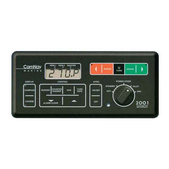
Page 38: Controls
ComNav 2001 Autopilot System CONTROLS The controls consist of a five position master select switch, and a 15 position membrane keypad. The controls operate as follows: MASTER SELECT SWITCH second delay, by ten degrees per second until the key is released. The function display will show a All power to the autopilot is turned off. - Page 39 ComNav 2001 Autopilot System MEMBRANE KEYPAD The control keys are used by pressing one of the At the maximum setting of '9', 10 degrees of RUDDER, COUNTER RUDDER, YAW, or rudder will be applied for a 1 degree per second TURN RATE keys.
- Page 40 ComNav 2001 Autopilot System ALARM CLEAR DODGE KEYS The autopilot will sound the alarm when an error condition exists. This condition will also be indicated on the display. The alarm may be The DODGE keys are used to dodge the vessel silenced by touching the ALARM CLEAR key.
- Page 41 ComNav 2001 Autopilot System Figure 8 - AUTOPILOT FRONT PANEL Figure 9 - AUTOPILOT REAR PANELREMOTE CONTROLS - 41- P/N 29010017 V1.0...
- Page 42 TURN RATE control. To display the type of special turn currently selected, place the remote in STANDBY, pull the Figure 10 - ComNav 101 Remote toggle switch to the U-TURN position and release it. Press either the red or green pushbutton to select a different type of special turn.
- Page 43 PILOT position. The pushbuttons can be used to alter the vessel's heading in one-degree steps, or by 10 degrees per second after holding the pushbutton for half a second. Figure 11 - ComNav 201 Remote - 43- P/N 29010017 V1.0...
-
Page 44: Remote Controls
The STANDBY, PILOT, AND NAV modes are the same as on the autopilot front panel, and the TILLER position permits direct control of the vessel's rudder angle, identical to the COMNAV 201 remote. The DODGE/U-TURN toggle switch operates identically to the COMNAV 101 remote. -
Page 45: Special Turns
ComNav 2001 Autopilot System SPECIAL TURNS When the autopilot is in the PILOT mode, pressing the U-TURN key together with either the red or green ARROW key for one second initiates the PRE-SELECTED type of special turn. EMERGENCY TURN When the second turn is complete, the vessel The Emergency Turn is selected by placing the should be retracing its own track in the water. - Page 46 ComNav 2001 Autopilot System SPECIAL TURNS U-TURN The U-Turn is selected by placing the autopilot in Pressing the U-TURN key and green ARROW the STANDBY mode, pressing the U-TURN key together for one second will start a similar key, followed by either the red or green ARROW turn to starboard.
-
Page 47: Operation
ComNav 2001 Autopilot System OPERATION For two seconds, the first thing you will see when The third operating mode is PILOT. When you the autopilot is turned on is the software revision turn the master select switch to this position, the number. - Page 48 ComNav 2001 Autopilot System Typical values for RUDDER, COUNTER DODGE key will cause the vessel to make a RUDDER, YAW and TURN RATE which panic turn in that direction. Pressing both seem to work on most vessels in the 30 to 60 foot DODGE keys when the vessel has turned far range are 4, 4, 1, and 6 respectively.
- Page 49 ComNav 2001 Autopilot System Device for ideas on making improvements. If the Nav. Device is set for automatic waypoint sequencing, the heading to steer will change when the next waypoint is selected, and the autopilot will turn the vessel to the new course.
- Page 50 ComNav 2001 Autopilot System operator’s control. At the flying bridge make sure When you want to go back to the main control that the remote switch is in the STANDBY mode. unit, leave the remote in the PILOT mode so the Press both pushbuttons on the remote control and vessel is under control.
-
Page 51: Gyrocompass Interface
(ie Sperry SR50) you need a different wire inside the gyrocompass depends on the type model of 2001 autopilot and a different interface. of output circuitry the gyrocompass has. If the Contact the factory or your dealer for assistance. - Page 52 ComNav 2001 Autopilot System Set the Synchro/Step selectors J1-J5 to the Plug the Interface output cable into the OPTION appropriate position accommodate receptacle on the rear of the autopilot. The Gyrocompass. If the gyrocompass has a Interface will automatically set itself to the output SYNCHRO output, they must all be in the voltage of the Gyro Transmitter.
-
Page 53: Wind Vane Interface
ComNav 2001 Autopilot System WIND VANE INTERFACE Read this section only if your autopilot is equipped with the optional windvane interface. OPERATION Press the WIND ON/SET key to engage the 10 degrees is displayed as 010 , while in wind windvane interface. - Page 54 S1, S2 and S3 leads (3 phase) or Sine, vane interface, all other installation and setup Reference and Cosine leads (2 phase). procedures are the same as for the standard 2001 autopilot. Hookup information on wind vanes we know to...
- Page 55 ComNav 2001 Autopilot System WINDVANE INTERFACE 3 Phase Outputs 2 Phase Outputs 6 Wire Cable plus Shield 5 Wire Cable plus Shield SINE YELLOW BLUE REFERENCE BLUE WHITE COSINE GREEN YELLOW INSTRUMENTS WITH AN NMEA 0183 WIND OUTPUT The autopilot must have 02.06 (01.15) software to it should indicate Stbd Tack, or vice versa, accept NMEA 0183 wind data.
- Page 56 CONVERTER (part number 93297) from we recommend it be done by your dealer. ComNav to tie into a Datamarine wind vane. Information on wire colours and other hookup information is included with the synchro converter.
- Page 57 Figure 15 to select using two 1K Ohm 1/4 Watt resistors as shown in the Sine/Cosine input; this is best done by your Figure 14. dealer. CONNECTION FOR NON-2001 FLUXGATE COMPASSES PLUG PIN NON-COMNAV COMNAV 2001 FLUXGATE...
- Page 58 ComNav 2001 Autopilot System Figure 14 - VDO WINDVANE HOOKUP Figure 15 - COMPASS INTERFACE PCB JUMPER SETTINGS The Sine and Cosine wires from the autopilot the reading on the autopilot display is increasing should be hooked in parallel with the YELLOW when the actual wind angle is decreasing, reverse and GREEN wires from the masthead unit.
-
Page 59: Error Checking
ComNav 2001 Autopilot System ERROR CHECKING The autopilot will display an error message and sound the alarm when any of the following conditions exist: - The vessel has fallen more than 20 degrees off course and has remained off course for more than 30 seconds. - Page 60 ComNav 2001 Autopilot System - This alarm is triggered if all three input lines from the gyrocompass go high or low simultaneously, and do not return to normal within two seconds. The autopilot will switch back to the magnetic compass, steering the...
- Page 61 ComNav 2001 Autopilot System ERROR CHECKING The autopilot is not receiving any recognizable data from the Nav. Device. This could be because 1) the Nav. Device is not programmed correctly; 2) the Nav. Device is not putting out any data; 3) No Data from Nav.
-
Page 62: Problem Solving
ComNav 2001 Autopilot System PROBLEM SOLVING Several different problems and possible solutions are outlined below. If the recommended solution does not solve the problem, return the autopilot to an authorized service centre for servicing. a) Check for power reaching the distribution box. - Page 63 ComNav 2001 Autopilot System PROBLEM SOLVING 3. cont... POWER STEER or higher mode. Check that the voltage on the PORT OUT and STBD OUT lines drop to less than 1.5 volts when their respective keys are pressed. The red and green PORT and...
- Page 64 ComNav 2001 Autopilot System a) Check that the compass cable is properly plugged 6. The displayed compass heading does not into the rear of the autopilot. follow the actual compass heading properly. Check compensating magnets, particularly heeling magnets, that are placed too close to the flux-gate sensor.
- Page 65 ComNav 2001 Autopilot System of the autopilot, or ON if it is a type 201 or 211 remote. PROBLEM SOLVING The autopilot is using a CT1T Type 1 Control 11. The rudder doesn't always move even Box, either as part of a CP1H Hydraulic Pumpset,...
- Page 66 ComNav 2001 Autopilot System ADDENDUM A Connecting a 1001F, 2200F or 2001F Autopilot System to a KVH AGDC DIGITAL GYRO COMPASS - 66- P/N 29010017 V1.0...
- Page 67 ComNav 2001 Autopilot System ADDENDUM B Connecting a 2001G, 2001GF, 2001GFC, 2001G1, 2001G1F, or 2001G1FC Autopilot system to a KVH AGDC DIGITAL GYRO COMPASS - 67- P/N 29010017 V1.0...
- Page 68 Medium size Slot Screwdriver. 2001 Installation and Operation Manual. The Autocomp procedure for 2001 Autopilots is detailed below. The procedure assumes that you have read the 2001 Installation and Operation Manual, and are familiar with the operation of the various controls on the Autopilot Head.
- Page 69 2) PAGE 17 - WARNING ADDED ABOUT ATTAINING A 10 TO 15 SECOND H.O. TIME. FEBRUARY 19, 1997 1) PAGE 28 - ADDED DRAWING SHOWING 2001 CPU BOARD LAYOUT MARCH 17, 1997 1) PAGE 4, 5 & 6 - NEW WARRANTY POLICY JUNE 20, 1997 - CORRECTED PAGE 67 DRAWING (TERMINALS 10 &...
Need help?
Do you have a question about the 2001 and is the answer not in the manual?
Questions and answers