
Related Manuals for ComNav 1440


Summary of Contents for ComNav 1440
- Page 1 1440/1460 Autopilot Systems Installation & Operation Manual COMPLIES WITH CE REGULATIONS PN 29010014 V2.3...
- Page 3 1440/1460 Autopilot Systems Installation & Operation Manual Document PN 29010014 V2.3...
- Page 4 First Printing: 1993 Revised: 2004 Revised: January/February & June 2009 Document PN 29010014 V2.3...
- Page 5 ELCOME Congratulations on your purchase of a ComNav Marine 1440/1460 Autopilot Systems! At ComNav, we are dedicated to reliability & quality in all our products, and proud of our prominence as a leader in the design and manufacture of marine autopilot systems. We promise to do our best to ensure your satisfaction with your new Autopilot System.
- Page 6 ComNav Marine 1440/1460 Autopilot Systems This page is intentionally blank. Document PN 29010014 V2.3...
-
Page 7: Table Of Contents
Compass Location ......................... 14 Power Connection ..........................14 Power Cable........................... 14 Grounding ............................14 1440 Receptacle & Control Head Installation ..................15 Mounting Clip Installation....................... 15 1460 Control Head installation ......................16 Fluxgate Compass Installation ......................17 Rotary Rudder Feedback Installation....................18 Outboard Feedback Installation ...................... - Page 8 ComNav Marine 1440 & 1460 Autopilot Systems Piloting with the 1440 or 1460 Autopilot.................51 Turning ON the 1440/1460 Autopilot:....................51 Turning the Autopilot OFF ........................51 Autopilot Modes ............................51 ............................ 51 TANDBY ........................... 51 OWER TEER ............................52 ILOT NAV M ............................
-
Page 9: Product Description
ComNav Marine 1440 & 1460 Autopilot Systems Product Description ComNav 1440 & 1460 Autopilot Systems When steering along a Course line in N are reliable, accurate and easy to use , the 1440/1460 use Heading aids to navigation. They feature four... -
Page 10: Before You Start
ComNav Marine 1440 & 1460 Autopilot Systems Before You Start Manual Conventions Thank you for buying the ComNav 1440 or 1460 Autopilot System. It will make In this manual, the names of the main boating safer, easier and more enjoyable components are capitalized. -
Page 11: Tools Required
ComNav Marine 1440 & 1460 Autopilot Systems Tools Required If you purchased a 1440/1460 with a The general tools & other items you will Hydraulic Reversing Pump, a list of the need while installing the system are: tools you will require specifically for the installation of the Pump is on page 27. - Page 12 ComNav Marine 1440 & 1460 Autopilot Systems 1460 System Diagram (with 1440 Second Station) Document PN 29010014 V2.3...
-
Page 13: Parts List
Note: Parts are not drawn to any scale. Processor. PN 20080003 For 1440 system packages: 1440 Control Head. PN 20080002. This part includes a flexible curly-cord, with a plug on the far end, wired to it; the cord can stretch to about 5 foot (1.5 m) long. - Page 14 ComNav Marine 1440 & 1460 Autopilot Systems ComNav Fluxgate Compass. PN 20320003. This part includes 40 feet (12.2 m) of cable wired to it. One Feedback unit or the other will be included: Rotary Rudder Feedback. PN 20330008. This part includes 50 feet (15.2 m) of cable wired to it.
- Page 15 • Power Cable. 7.5 feet (2.3 m) of cable (labelled “5”), for connecting supply voltage to the Processor. • Accessory Kit. The 1440 kit (PN 20080005) contains a Mounting Clip for the 1440 Control Head, and some lubricant for the Head’s plug. The 1460 kit (PN 20080006) contains a mounting bracket &...
- Page 16 ComNav Marine 1440 & 1460 Autopilot Systems Plugging the 1440 Control Head curly-cord cable into the socket on Cable #1 1460 Control Head with attached Cable #1 Document PN 29010014 V2.3...
-
Page 17: Installation Instructions
ComNav Marine 1440 & 1460 Autopilot Systems Installation Instructions Caution Using ordinary electric tools near water is VERY dangerous! To minimize the dangers of electric shock and personal injury, we recommend using cordless rechargeable tools or hand tools. 1440/1460 Autopilot System... -
Page 18: Compass Location
ComNav Marine 1440 & 1460 Autopilot Systems Compass Location Route Cable #5 to the Processor location. When choosing a location for the Keep the breaker turned off until you Compass, try to locate it as close as have connected the wires to the breaker. -
Page 19: 1440 Receptacle & Control Head Installation
ComNav Marine 1440 & 1460 Autopilot Systems 1440 Receptacle & Control Head Installation The receptacle is attached to the Control Head’s end of Cable #1. The diagram to the right shows the receptacle mounted in a panel. Mount the receptacle near... -
Page 20: 1460 Control Head Installation
ComNav Marine 1440 & 1460 Autopilot Systems 1460 Control Head installation The 1460 Control Head can either be surface-mounted on a suitable flat-surface panel at the main steering station (for example, on the dashboard), or flush-mounted in an opening in the panel. The panel must be less than about ½” (15 mm) thick. -
Page 21: Fluxgate Compass Installation
ComNav Marine 1440 & 1460 Autopilot Systems Fluxgate Compass Installation Initially, mount your Fluxgate Compass using strong adhesive tape or some other temporary, non-marking fastener. reason for this is that It may be necessary to relocate your compass after you have done the Setup Routine. -
Page 22: Rotary Rudder Feedback Installation
ComNav Marine 1440 & 1460 Autopilot Systems Rotary Rudder Feedback Installation If you have a 1440 or 1460 System with an Outboard Feedback, please go to page 21. Select the following parts from your 1440 or 1460 package: Brass Ball Joint... - Page 23 ComNav Marine 1440 & 1460 Autopilot Systems Mounting the Rudder Feedback In the diagram above notice that: To align the Rudder Feedback Arm & the Rudder Post Arm correctly, you may need • the Rudder Feedback Arm is above to make a mounting base for the Rudder the cable entry gland Feedback.
- Page 24 ComNav Marine 1440 & 1460 Autopilot Systems Assembling the Rudder Feedback Arm: Loosen the adjustment block that keeps Measure the approximate diameter of the two pieces of the Rudder Feedback your rudder post in inches. Linkage from sliding. The Rudder Post Arm has several holes Snap the Rudder Feedback Linkage onto drilled through it.
-
Page 25: Outboard Feedback Installation
ComNav Marine 1440 & 1460 Autopilot Systems Outboard Feedback Installation If you have a Rotary Rudder Feedback, please go to page 18. Introduction Outboard Feedback sends The Outboard Feedback is provided with information about the rudder or propeller 30 feet (9.1 m) of cable. - Page 26 ComNav Marine 1440 & 1460 Autopilot Systems Mounting Hardware Mount the Outboard Feedback so that it will not be damaged when the motor is tilted for trailering. Mounting Outboard Feedback Use a tape measure or ruler to position mounted with the sliding rod facing either the Outboard Feedback rod so that it left or right.
- Page 27 ComNav Marine 1440 & 1460 Autopilot Systems Adjust the position of the Outboard Feedback so that the end of the sliding rod is flush with the Stainless Bracket. Screw the nut onto the threaded rod at the end of the Outboard Feedback.
- Page 28 ComNav Marine 1440 & 1460 Autopilot Systems Outboard Feedback Mounting to Front-Mount Cylinder Document PN 29010014 V2.3...
-
Page 29: Rudder Drive
ComNav Marine 1440 & 1460 Autopilot Systems Rudder Drive The next step is to install the Rudder Drive. • If the system you purchased includes a Reversing-Motor Hydraulic Pump, follow the instructions in this section. • If your system came with a Cable Drive, follow the Installation Instructions that came with that. -
Page 30: Pump Models & Specifications
ComNav Marine 1440 & 1460 Autopilot Systems Pump Models & Specifications There are two models of ComNav pumps, defined by the maximum size of cylinder they can be used with: 18 in or 30 in . Each model also has a choice for the operating voltage of the pump’s motor: 12 or 24 VDC. -
Page 31: Types Of Steering Systems
ComNav Marine 1440 & 1460 Autopilot Systems Types of Steering Systems There are two general types of steering systems: Two Line systems, and Three Line systems. The pump connection to the steering system is different for each type. There are separate instructions below for each type (see pages 30 & 31). -
Page 32: Notes & Cautions
ComNav Marine 1440 & 1460 Autopilot Systems Notes & Cautions Before beginning to connect the pump to the steering system, review the following points: • Cap or cover the ends of hoses with a clean rag before pushing them between bulkheads. -
Page 33: Installing The Pump
ComNav Marine 1440 & 1460 Autopilot Systems Installing the Pump Installation of the pump consists of: • Finding a mounting location for the pump • Partially draining the steering system • Mounting and connecting the pump to the existing steering lines •... -
Page 34: Hydraulic Connections
ComNav Marine 1440 & 1460 Autopilot Systems Hydraulic Connections Next, make the appropriate hydraulic connections, according to whether you have a Two Line or Three Line Steering System. Hydraulic Connections for Two Line Steering Systems 2 Line Steering System Connections... - Page 35 ComNav Marine 1440 & 1460 Autopilot Systems Hydraulic Connections for Three Line Steering Systems 3 Line Steering System Connections Delivery Lines: In the above diagram, Ports A and B are the input/output ports of the pump, and must be connected to the steering lines between the steering cylinder and the Uniflow valve.
-
Page 36: Fill And Bleed
This will press as much oil as possible into the system. It will not damage the pump. The 1440 or 1460 will drive the pump past the electronic rudder limit only Adding Capacity bLEd when the display shows Document PN 29010014 V2.3... - Page 37 ComNav Marine 1440 & 1460 Autopilot Systems Bleeding cylinder, rod moving left Bleeding cylinder, rod moving right. Document PN 29010014 V2.3...
- Page 38 ComNav Marine 1440 & 1460 Autopilot Systems 8. Refill your steering system from the 13. Close all bleeding screws or nipples. highest reservoir. Clean up any oil spills and wipe fittings clean. Remove any buckets 9. Adjust the bleeding screws so that...
-
Page 39: Wiring The Processor
ComNav Marine 1440 & 1460 Autopilot Systems Wiring The Processor Place the Processor in front of you with the lettering right side up. Remove the four Phillips screws from each end. Remove the end pieces of the Processor enclosure. Looking into the open ends of the Processor you will see several green terminal strips. -
Page 40: Right Side Connections
Caution: there are some differences in hand end of the Processor. the colour codes of the cable types that can be used for Cable 1 (the 1440 Note that there is an empty socket that Receptacle, & the 1460 Head), and Cable does not have a terminal strip. - Page 41 BLACK GREY DRIVE P2 N/C ** PINK DRIVE P1 N/C ** GREEN GREEN +12V +12V * If the compass reading is reversed, swap these two wires ** These wires must not be connected to non-ComNav compasses Document PN 29010014 V2.3...
-
Page 42: Left Side Connections
ComNav Marine 1440 & 1460 Autopilot Systems Right Side, Cable 3 (Rudder Feedback) to J7 Connecting the Ground Wire Left Side Connections In the Cable 5 diagram below, the Ground Next, do the left side wiring. Remove the is the green wire. It is connected to the... - Page 43 ComNav Marine 1440 & 1460 Autopilot Systems Left Side, Cable 4 (Pump Motor) Please see the Appendices for wiring to other types of motors, or solenoids. Left Side, Cable 5 (Power) Document PN 29010014 V2.3...
-
Page 44: Connecting The Navigation Cable
ComNav Marine 1440 & 1460 Autopilot Systems Left Side, Optional Navigation Input Connection Connecting the Navigation Cable The optional navigation data input cable Use the diagram above to wire the may be connected at this time. Parts for navigation input. The terminal strip for this are in the Accessory Kit. -
Page 45: Mounting The Processor
ComNav Marine 1440 & 1460 Autopilot Systems Powering Up the System Mounting the Processor Turn on the breaker for the Autopilot or Once you have completed and checked connect the Power cable to the breaker. the wiring, you are ready to mount the Processor. -
Page 46: Fuse Replacement
Autopilot needs repair. To replace the fuse: 1. Turn off the power to the 1440/1460. 2. Loosen the right side watertight glands Processor, remove the end cap. Disconnect the plugs. -
Page 47: Setting Up The Autopilot System
Both the 1440 & 1460 have the same Steps in their Setup Routines, and show the same information on the Control Head display & key lights, at each Step. -
Page 48: Locating The "Flush Key
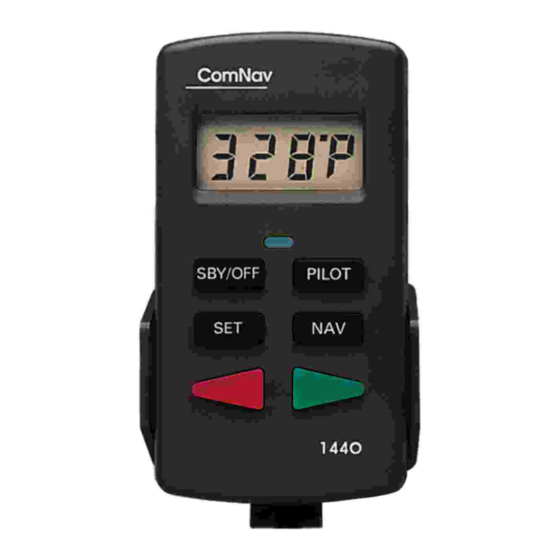
Control Head’s surface, to prevent accidental activation). The Flush Key, on a 1440 Control Head, is located immediately below the LCD display: The Flush Key, on a 1460 Control Head, is located immediately below the SET and NAV keys: Document PN 29010014 V2.3... -
Page 49: Setting Up - Step By Step
ComNav Marine 1440 & 1460 Autopilot Systems Setting Up – Step by Step 1. Press and hold the Flush Key (see 2. Turn the steering wheel fully to previous page & below). Press and Starboard. Press the Set Key. hold the Pilot Key until the display... - Page 50 ComNav Marine 1440 & 1460 Autopilot Systems 3. Turn the steering wheel fully to Port. 4. Move the steering wheel to the Press the Set Key. mid-ships position. Position the wheel as if you were going Dead Ahead, in a straight line.
- Page 51 ComNav Marine 1440 & 1460 Autopilot Systems CAUTION In the Step 5, the 1440/1460 will move the steering system through its full range of motion. If you need to stop it, pressing and holding the SBY/OFF KEY will immediately stop the steering movement.
- Page 52 ComNav Marine 1440 & 1460 Autopilot Systems 7. Press the Set Key The Autopilot will then display a message showing the type of compass it detected: • If you have a magnetic compass the display will show (magnetic) for a few seconds.
-
Page 53: Fluxgate Compass Compensation
ComNav Marine 1440 & 1460 Autopilot Systems Fluxgate Compass Compensation In order to complete the setup of a 10. Slowly turn the boat in as small a Fluxgate Compass, it is necessary to take circle as possible. Maintain as steady a short trip with your boat. -
Page 54: Align To Magnetic North
ComNav Marine 1440 & 1460 Autopilot Systems Align to Magnetic North nort 11. The Autopilot will display The Autopilot’s Heading display is now (North). aligned to the magnetic direction values sensed by your fluxgate compass, or magnetic sensor. The Autopilot will turn off. -
Page 55: Piloting With The 1440 Or 1460 Autopilot
ComNav Marine 1440 & 1460 Autopilot Systems Piloting with the 1440 or 1460 Autopilot Autopilot Modes This section will introduce you to your ComNav Autopilot. The very first thing to learn about your 1440/1460 Autopilot is the various modes Learn its operations step by step; you will it can be used in. -
Page 56: Pilot Mode
ComNav Marine 1440 & 1460 Autopilot Systems In P , the rudder angle Steering Control Settings OWER TEER and the rate of turn will increase as long In the P & NAV M , the ILOT ODES as you hold the Red or Green Key down. -
Page 57: What Is Good Steering Control
ComNav Marine 1440 & 1460 Autopilot Systems What is Good Steering Control? Determining the Response Settings When your ComNav Autopilot is working Move your boat to an open area of water properly, it will steer your vessel in a away from docks and other boats. - Page 58 ComNav Marine 1440 & 1460 Autopilot Systems Press the Set Key. For a five second To decrease the Rudder Response FASt Sensitivity: interval, the display will read either SLOU (fast) or (slow). This is the Rudder Press the Set Key. The display will show...
- Page 59 ComNav Marine 1440 & 1460 Autopilot Systems ⇒ If your vessel is gradually falling To decrease the Counter-Rudder Response Sensitivity: away from the Course line, like this: Press the Set Key. The display will show SLOU for five seconds. During the five...
-
Page 60: Turns And Changing Course
ComNav Marine 1440 & 1460 Autopilot Systems Turns and Changing Course The speed of the turn will be governed by the Autopilot. At this point – while still moving slowly in Autopilot will turn the vessel at 5º per , and with the Responses set... -
Page 61: Setting The Fast Speed Rudder Response & Counter- Rudder Sensitivities
ComNav Marine 1440 & 1460 Autopilot Systems Fast Speed Turns and Course Setting the Fast Speed Rudder Changes Response & Counter- Rudder Sensitivities All the Autopilot’s Turn, Course Change Press the Pilot Key to steer a course by and Dodge features described above for compass. - Page 62 ComNav Marine 1440 & 1460 Autopilot Systems Correct Vessel Response During a Course Change Document PN 29010014 V2.3...
-
Page 63: Adjusting The Digital Rudder Angle Indicator (Rai)
ComNav Marine 1440 & 1460 Autopilot Systems RAI Offset Adjusting the Digital Rudder Angle Indicator (RAI) Many vessels always need the rudder positioned to Port or Starboard by a small 1440/1460 also provides amount. This slightly offset rudder electronic Rudder Angle Indicator. -
Page 64: The Navigation Interface
ComNav Marine 1440 & 1460 Autopilot Systems The Navigation Interface 1440/1460 Autopilot Note: ComNav Autopilots fully conform to navigation data information sent to it from the syntax of the NMEA 0183 Standard’s a navigation device (such as a GPS language. -
Page 65: Using The Navigation Interface
ComNav Marine 1440 & 1460 Autopilot Systems Incorrect or No Navigation Data Using the Navigation Interface If the autopilot consistently beeps every To be safe, learn to use your Navigation ndAt five seconds and displays Interface at slow speeds, away from other Data) then it is not receiving usable data vessels. -
Page 66: Cross Track Error
ComNav Marine 1440 & 1460 Autopilot Systems Cross Track Error Cross track error is a measure of the If necessary, change the direction of distance your boat has fallen away from cross track error. If the Autopilot begins the Course line. -
Page 67: Nav Mode Display
ComNav Marine 1440 & 1460 Autopilot Systems Display • Cross-track quality The first 2 digits (XXx) denote the source of the cross track data (if any) and are used as a relative priority. The higher the value, the better the data source. The first digit (Xxx) is used to... - Page 68 ComNav Marine 1440 & 1460 Autopilot Systems This page is intentionally blank. Document PN 29010014 V2.3...
-
Page 69: Operation Commands
ComNav Marine 1440 & 1460 Autopilot Systems Operation Commands COMMAND ACTION RESULT Steer by compass 1440/1460 is off or in Boat will settle on course. nnnP TANDBY Display will show Point bow and press Pilot Key. Turn OFF Press and hold SBY/OFF Immediately upon pressing Key for two seconds. - Page 70 ComNav Marine 1440 & 1460 Autopilot Systems COMMAND ACTION RESULT Dodge: left In P or N Vessel turns left. ILOT Press and hold Red Key. When key is released, the display nnnd ILOT Display will show: returns and vessel returns Release Red Key to return to original course.
-
Page 71: Adjustment Commands
ComNav Marine 1440 & 1460 Autopilot Systems Adjustment Commands COMMAND ACTION RESULT Rudder sensitivity: In P or N Autopilot will steer with a ILOT increase “harder” turn to correct course Press Set Key twice. deviations, causing a shorter Press Green Key. -
Page 72: 1440 & 1460 Control Head Messages
Fluxgate compass detected. Fast Speed Rudder Response: rudder value (digit)(digit) Full reset. The 1440 or 1460 requires that the Set-up Routine be FRST repeated. After the Set-up Routine is done, the problem should be fixed. If this error message continues to occur, take your Autopilot to a ComNav dealer for servicing. - Page 73 1460 will turn off the steering outputs. When the temperature falls, the steering outputs will turn back on. We recommend that you have the Autopilot serviced by a ComNav dealer before it is used again. The supply voltage is less than 9.5 Volts. The Autopilot cannot LBAT operate reliably.
- Page 74 ComNav Marine 1440 & 1460 Autopilot Systems Message Description No compass error during Dockside Set-up. Check: • The compass cable is connected to the correct Processor terminals. • There are no poor or loose connections on the Compass N[ER cable.
- Page 75 ComNav Marine 1440 & 1460 Autopilot Systems Message Description SL0U Momentarily indicates that Slow Speed Rudder Response has been selected -14-* Sign-on message Slow Speed Rudder Response: rudder value (digit)(digit) While adjusting compass, if the autopilot will not stop displaying...
-
Page 76: Problems Without An Error Code
The random occurrence of this problem is possible but unlikely. If this problem occurs twice, your Autopilot may need servicing. Contact your ComNav dealer. The Autopilot starts, the The 1440 or 1460 Control Head may be disconnected. Control Head display goes safety reasons,... -
Page 77: Connections To 4 And 5 Wire Motors
ComNav Marine 1440 & 1460 Autopilot Systems Appendix A Connections to 4 and 5 Wire Motors Document PN 29010014 V2.3... -
Page 78: Connections To 4 And 5 Wire Motors (Using A Clutch Or Lockup Valve)
ComNav Marine 1440 & 1460 Autopilot Systems Appendix B Connections to 4 and 5 Wire Motors (using a clutch or lockup valve) Document PN 29010014 V2.3... -
Page 79: Connections To Solenoid Valves
ComNav Marine 1440 & 1460 Autopilot Systems Appendix C Connections to Solenoid Valves Document PN 29010014 V2.3... -
Page 80: Remote Operation
Control Head from one location to another. It is also possible to mix the types of Control Heads on a 1440 or 1460 System; a 1460 Second Station Kit may be used on a 1440 System, and either or both of the 1440 Kits may be used on a 1460 System. - Page 81 S HIE LD S HI E LD N o t e : Y e l l o w w i r e N O T u s e d . Right Side, Optional 1440 Second Location Connections (J6) Document PN 29010014 V2.3...
-
Page 82: Connecting The Nmea 0183 Heading Output
Connecting the NMEA 0183 Heading Output Location of terminal strip J5 The 1440/1460 Autopilot has a connector that outputs NMEA 0183 heading information, for use by external devices such as Radars. Heading data is transmitted once per second, using two NMEA sentences: HDM (magnetic heading) and HDG (magnetic heading, deviation &... -
Page 83: Connecting A Rudder Angle Indicator
ComNav Marine 1440 & 1460 Autopilot Systems Appendix F Connecting a Rudder Angle Indicator SIGNAL RETURN Right Side, Optional RAI connection The cable gland for a rudder angle indicator is in your Accessory Bag. We do not supply a cable for this installation but recommend a 22 AWG, two-conductor cable; the cable must be round in order to make a water-tight seal. - Page 84 ComNav Marine 1440 & 1460 Autopilot Systems This page is intentionally blank. Document PN 29010014 V2.3...
-
Page 85: Warranty
ComNav Dealer, and such installation has been inspected by an Authorized ComNav Dealer; the Limited Warranty Registration Card has been returned to ComNav within 14 days of the date of purchase of the Equipment by the Purchaser with Part I thereof having been completed by the Purchaser, and with the Extended Limited Warranty Card having been completed and signed by an authorized ComNav Dealer and returned to ComNav within 14 days of that inspection;... - Page 86 ComNav within 10 days of the date upon which the defect first became known to the Purchaser. Notices sent by mail will be deemed to be received by ComNav on the seventh (7th) day first following the date of posting in North America and on the tenth (10th ) day next following the date of posting anywhere else in the world.
- Page 87 Purchaser; No refund of the purchase price for the Equipment will be made to the Purchaser unless ComNav is unable to remedy the defect after having a reasonable number of opportunities to do so. Prior to...
- Page 88 PURCHASER MAY ALSO HAVE OTHERS WHICH VARY FROM STATE/JURISDICTION TO STATE/JURISDICTION. This Agreement is a legal contract between you (the “Purchaser”) and ComNav. By retaining the Equipment for more than thirty (30) days and/or installing and/or using the Equipment, the Purchaser agrees to be bound by the terms of this Agreement.
-
Page 89: Ce Compliance
ComNav Marine 1440/1460 Autopilot Systems CE COMPLIANCE This product is in compliance with the Electro-Magnetic Compatibility (EMC) standards of the European Community, and bears the CE mark. It was tested according to the applicable sections contained in: CE Directives IEC 945:1994, BS EN 60945:1996... - Page 90 ComNav Marine 1440/1460 Autopilot Systems OTES You can use this table to record the serial numbers of the components of your system, setup settings, any notes you made during installation, and any other information you might want to keep handy.
Need help?
Do you have a question about the 1440 and is the answer not in the manual?
Questions and answers