Sign In
Upload
Manuals
Brands
ComNav Manuals
Autopilot System
P4 Remotes Series
ComNav P4 Remotes Series Autopilot System Manuals
Manuals and User Guides for ComNav P4 Remotes Series Autopilot System. We have
2
ComNav P4 Remotes Series Autopilot System manuals available for free PDF download: Installation And Operation Manual, Installation & Operation Manual
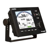
ComNav P4 Remotes Series Installation And Operation Manual (200 pages)
Advanced Autopilot Systems
Brand:
ComNav
| Category:
Autopilot System
| Size: 4 MB
Table of Contents
Welcome
2
About this Manual
3
Typefaces, Common Phrases and Terms
3
Manual Format
4
Document History
5
Table of Contents
6
List of Figures
12
List of Tables
14
How Autopilots Work
18
Basic Autopilot System
19
Figure 1 - Basic Autopilot System
19
Autopilot Operation: Maintaining a Heading and Current Effects
20
Figure 2 - Heading Change in AUTO Mode
22
Power Steer
25
System Overview
26
Figure 3 - P4 System Block Diagram
28
Control Head
29
Figure 4 - Control Head
29
Signal Processor Unit
30
Figure 5 - the P4 SPU with Wiring and Diagnostic Covers Removed
30
Compasses
31
G2 and G2B GPS Compasses
31
Figure 6 - G2 GPS Compass
31
Figure 7 - Navigator G2 Display Head
32
Fluxgate Compass
33
Figure 8 - Navigator G2 Distribution Unit
33
Figure 9 - Fluxgate Compass
33
Magnetic Compass Sensor
34
Magnetic Compasses
34
Figure 10 - Magnetic Compass Sensor
34
Figure 11 - Externally Gimballed Magnetic Compass with Binnacle
34
Other Compasses
35
Rudder Followers
35
Standard Rotary Rudder Follower and Rudder Linkage
35
Heavy Duty Rotary Rudder Follower
35
Figure 12 - Rotary Rudder Follower
35
Jog Levers
36
Rudder Angle Indicator (RAI) - 3
36
Figure 13 - Heavy Duty Rotary Rudder Follower
36
Figure 14 - Jog Lever
36
Figure 15 - External Rudder Angle Indicator - 3" Model
37
Rudder Drives and Interfaces
38
CT7 Thruster Interface
38
Figure 16 - CT7 Interface
38
Other Drive Boxes
39
Figure 17 - Drive Boxes to Meet All Needs
39
Pumps and Drives
40
Other Equipment
40
Figure 18 - Hydraulic Pump and Solenoid Value
40
Figure 19 - Cable Drives
40
Figure 20 - Continuous Running Electric Pump
40
Installation
43
Basic Requirements
43
Steering System
43
Power Supply
43
Special Tools
43
Fasteners
43
Control Head
44
Electrical Connection
44
Signal Processor Unit
44
Compasses
45
Electrical Connection
46
Magnetic Compass and Sensor
46
Rudder Follower
47
Rotary Rudder Follower
48
Figure 21 - Rudder Follower Linkage Geometry
48
Heavy Duty Rotary Rudder Follower
49
Other Equipment
49
Signal Processor Unit
50
Wiring the SPU - General
50
Connectors on the SPU
50
Figure 22 - SPU Connector Wiring Label
51
Wiring the System
52
Power Supply
52
Figure 23 - Typical Battery Connection to SPU
52
Figure 24 - Typical Battery Connection to Head
53
Figure 25 - Typical Battery Connection to Drive Boxes
54
Figure 26 - Reducing Supply Voltage Losses
54
Input and Output Connections
55
Jog Levers
55
Figure 27 - Wiring Connections for SPU to N2K Networks
55
Figure 28 - Wiring Connections for Jog Levers
56
Figure 29 - Wiring Connections for Four-Way Valves with Jog Levers
56
Compasses
57
Rudder Follower
57
Figure 30 - Wiring Connections for Analog Compasses
57
Figure 31 - Wiring Connections for Rudder Followers
57
Rudder Angle Indicators
58
Drive Outputs
58
Reversing DC Motor Hydraulic Systems
58
Figure 32 - Wiring Connections for Rudder Angle Indicators
58
Linear Actuators or Mechanical Rotary Drives
59
Figure 33 - Wiring Connections for Reversing DC Motors
59
Figure 34 - Wiring Connections for Linear Actuators or Mechanical Rotary Drives
59
Shunt-Field Reversing Motors
60
Standard Four-Way Solenoid-Activated Hydraulic Valves
60
Figure 35 - Wiring Connections for Shunt Field Reversing Motors
60
Figure 36 - Wiring Connections for Standard Four-Way Solenoid Valves
60
Solenoids
61
Figure 37 - Wiring Connections for Constant Running Electric Pump
61
Azimuth Drives, Surface Piercing Drives and Jet Drives
62
External Alarm Output
62
Figure 39 - Wiring Connections for A.C. Solenoids
62
Figure 40 - External Alarm, Using SW'D B- Output
62
Figure 41 - External Alarm, Using SW'D B+ Output
63
Power Failures
64
Figure 42 - External Alarm, SW'D B- Output - with Power Fail Option
64
Figure 43 - External Alarm, SW'D B+ Output - with Power Fail Option
64
Speed Mode and Timing Outputs
65
Navigation Data
66
Figure 44 - Typical NMEA 0183 Connections
66
Signal Names
67
RS-422 Electrical Interface
67
Typical RS-422 Signals
68
Figure 45 - Typical NMEA 0183 RS-422 Transmission
68
RS-232 Electrical Signals
69
LED Status Indicators
69
Other Connections
69
Post-Installation Checks
69
Getting Started
72
Autopilot Operations
73
Power On/Of
73
Figure 46 - Introductory Display
74
Table 3A - Turning off P4 System
74
Using the Control Head - LCD Screen and Buttons
75
Figure 47 - Using the Control Head
75
Operating Modes and Menus
76
Advanced Operations
77
Figure 48 - Typical Work Mode Screen (Engaged)
78
Figure 49 -Work Mode Menu
80
Figure 50 - a Typical Menu
81
Alarm Clear
82
System Setup Menu
82
To Repair and Reset
87
Connect GNSS (N2K) Compass to System
88
Connect Rotary Follower Unit to System
89
Magnetic / Fluxgate Compass and Rotary Feedback Flollower
89
Connect Fluxgate Compass to the SPU
90
For Non-Comnav Devices
91
Network System Information
95
AP Network
97
SPU Dockside Menu
100
Reset
101
Vessel Type
101
Table 4 - Vessel Type
101
Compass Setup
102
Drive Setup
102
Exit
102
Alarm O/P (Alarm Output)
102
Thrust MAX
102
Language
102
Setup Procedures
103
Vessel Type
103
Drive Setup
104
Figure 51 - Set Vessel Type
104
Compass Setup
107
Figure 52 - Set Compass Type
107
Analog Compass
108
NAV1 Port
108
NAV1 or NAV2 Port for General NMEA0183 Compass
109
Bandwith of a NMEA Compass Connection
110
Table 5 - Compass Types
112
Compass Setup on the Water
113
Compensation for Magnetic Deviation
113
Magnetic Compass Sensor
113
Fluxgate Compass
114
Compass Calibration
115
Sea Trials
117
Sea Trials Procedures and Adjustments
117
Basic Operations
122
Control Head LCD Screen and Buttons
123
Figure 52A - Using the Control Head
123
Operating the System
125
Mode Menus
125
Figure 53 - a Typical Menu
126
Rudder Angle Indicator
127
Power on
128
Power off
128
Figure 54 - Standby Button
128
Figure 55 - Power on Sequence
128
Standby Menu
129
Auto Menu
131
NAV Menu
132
Work Menu
133
Standby Menu
134
Station Lock
134
Default Turn
134
Compass Source
134
Compass Cal (Compass Calibration)
134
Figure 56 - Standby Menu (Pages 1,2 & 3)
134
Backlight Level
135
Watch Alarm
135
Fishzag Time
135
Battery
135
Power Steer Mode
135
Power Steer Menu
136
Stdby/P.str Limits (Power Steer Rudder Limits)
136
Figure 57 - Typical Power Steer Mode Screen
136
Figure 58 - Power Steer Menu
136
Auto/Nav Limits
137
RAI Offset
137
Auto Mode
137
Figure 59 - Typical Auto Mode Screen
137
Rudder Gain
138
Figure 60 - Guidelines for Setting Counter Rudder
138
Turn Rate
139
Parameter Set
139
Speed Trip Pt (Speed Trip Point)
140
Speed Source
140
ALC (Automatic Leeway Correction)
140
Thruster Assist and Gain
140
Nav Mode
140
Figure 61 - HI and lo Speed Icons (Left of Rudder Angle Indicator)
140
Figure 62 - Typical NAV Mode Screen (Normal Display)
141
Nav Menu
142
Nav Source
142
XTE Limit (Cross-Track Error Limit)
142
Waypt. Arrival (Waypoint Arrival)
142
Figure 63 - Nav Menu, Pages 1 and 2
142
Correction
143
XTE Sense (Cross-Track Error Sense)
143
Max Correction
143
Commanded Heading Displayed
144
Correction Set to CTS - Steering a Direct Bearing
144
Figure 64 - Steering with Correction Set to CTS
144
Correction Set to XTE - Cross-Track Error Steering
145
Figure 65 - Steering with Correction Set to XTE
145
Correction Set to both - Steering To/Along a Track
146
Figure 66 - Response of Vessel to a Large Cross-Track Error
146
Figure 67 - Steering with Correction Set to both
147
Alternate NAV Display
148
Dodge
148
Figure 68 - Typical NAV Mode Screen (Alternate Display)
148
Figure 69 - a Dodge in Progress (in AUTO Mode)
149
Figure 70 - Vessel Track During a Dodge Manoeuvre in AUTO Mode
149
Jog Lever Turns
150
Figure 71 - Typical Jog Lever Activated Screen
150
Advanced Operations
152
WORK Mode
153
Figure 72 - Typical WORK Mode Screen (Engaged)
154
Work Menu
156
Rudder Bias
156
Autotrim
156
Work Trip Pt. (Work Trip Point)
156
Figure 73 - WORK Mode Menu
156
Rudder Scale (Rudder Scale Factor)
157
Work Mode State
157
Special Turns
157
Figure 74 - Typical Special Turn Query
157
U-Turn
158
Figure 75 - U-Turn Query
158
Figure 76 - U-Turn Vessel Path
158
Circle Turn
159
Figure 77 - Circle Turn Query
159
Figure 78 - Circle Turn Vessel Path
159
M.O.B. - man Over-Board
160
Figure 79 - M.O.B. Turn Query
160
Figure 80 - M.O.B. Turn Vessel Path
160
Fishzag
161
Figure 81 - Fishzag Turn Query
161
Figure 82 - Fishzag Turn
161
Multiple Control Heads and Auxiliary Controller
162
Station Lock/Unlock
162
Figure 83 - Station Lock Icons on Main (Left) and AUX Control Head (Right)
162
Watch Alarm
163
Entering the Password
164
Changing the Password
164
Care and Maintenance
166
Cleaning and Appearance
167
Protection of Wires and Cabling
167
Periodic Checks
167
Fuse Replacement
168
Appendices
170
Appendix 1 _____________________________________________________________
171
NMEA 0183 Sentences Accepted and Transmitted by the Autopilot
171
Messages Accepted171
171
Table 8 - NMEA 0183 Sentences Accepted by the P4
172
Messages Transmitted174
174
Appendix 2 _____________________________________________________________
175
Error Messages175
175
Table 10 - Warning Messages
175
Table 11 - Error Messages
176
Table 12 - Critical Error Messages
177
Appendix 3 _____________________________________________________________
178
Diagnostic Leds
178
Table 13 - Diagnostic Leds
178
Appendix 4 _____________________________________________________________
179
Upgrading Firmware
179
Appendix 5 _____________________________________________________________
180
General Specifications
180
Compass Safe Distances
181
CE Compliance
182
Warranty Information
183
Index
187
User Notes and Settings
190
Advertisement
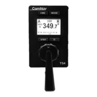
ComNav P4 Remotes Series Installation & Operation Manual (40 pages)
Full Follow Up Remote And Non-Follow up Joystick Remote for P4 Autopilot Systems
Brand:
ComNav
| Category:
Remote Control
| Size: 0 MB
Table of Contents
Installation & Operation Manual
3
Welcome
3
Document History
4
Table of Contents
5
List of Figures
7
List of Tables
7
Introduction
9
Figure 1 - P Series Autopilot System (Partial Diagram)
11
Overview of the TS4 Remote
11
About this Manual
12
Typefaces, Common Phrases & Terms
12
Manual Format
13
Installation
15
Technical Requirements
17
Caution Warning
17
Electrical Connections
17
Network Connection in a P4 System
17
Figure 3 - TS4 / NF4 LCD Screen
18
Operation
19
User Interface
21
Current Mode
21
Display Controls
22
Brightness
22
Day/Night Mode
22
Normal Usage
23
Taking Command
23
Modes of Operation
23
STANDBY (STDBY) Mode
24
TILLER Mode
24
AUTO Mode
24
Change Course in NF4
25
Work Mode
25
Course Recall
25
NAV Mode
25
Alarm Clear
25
Initial Mode
26
Shortcut Functions in NFU
26
Operating Menu
26
Off Mode or Sleep Mode
27
Appendices
29
Multi SPU Installation
31
Care & Maintenance
31
Specifications
31
Index
33
User Notes
37
User Notes
39
Advertisement
Related Products
ComNav Commander P2
ComNav Commander P2VS
ComNav P300
ComNav 1001
ComNav 1101
ComNav 1201
ComNav 1420
COMNAV 1440
COMNAV 1460
ComNav 1500
ComNav Categories
Receiver
Autopilot System
Marine Equipment
Compass
Transceiver
More ComNav Manuals
Login
Sign In
OR
Sign in with Facebook
Sign in with Google
Upload manual
Upload from disk
Upload from URL