
Related Manuals for ComNav 1440


Summary of Contents for ComNav 1440
- Page 1 INSTALLATION and OPERATION MANUAL COMNAV 1440/1460 AUTOPILOTS COMNAV 1460 AUTOPILOT COMNAV 1440 AUTOPILOT COMPLIES WITH CE REGULATIONS P/N 83468 V1.2...
- Page 2 In Canada or the USA Toll Free Phone: 1-800-428-0212 Toll Free Fax: 1-800-470-9611 E-Mail: sales@comnav.com Web Site: www.comnavmarine.com Owner's Manual for Installation and Operation of 1440/1460 Autopilot Part Number: 83468 First Printing: May 1999 Revised: June 2000 COMPLIES WITH CE REGULATIONS...
- Page 3 WARRANTY NOTICE Prior to the installation and/or operation of the Equipment, ensure that you read, understand and accept the conditions of the warranties as detailed on the following pages. OPERATORS WARNING This Autopilot will automatically steer your vessel however, it is only an aid to navigation.
- Page 4 June 15, 2000 This document, ComNav Part No. 83468, V1.2, is the approved Installation and User's Manual for use with the ComNav 1440/1460 Autopilot. Where versions of this manual exist in other languages, the English version shall be considered authoritative. Suggestions for changes or improvements may be directed to the Sales Manager at ComNav Marine Ltd.
-
Page 5: Table Of Contents
Rotary Rudder Feedback Installation..........................27 Attaching the Rudder Feedback Linkage ...........................29 Outboard Feedback Installation ............................33 Wiring the Processor ................................37 PILOTING WITH THE 1440 OR 1460 AUTOPILOT ....................61 Setting Slow Speed Rudder Response..........................62 Turns and Changing Course..............................63 Setting Fast Speed Rudder & Counter-Rudder Response ....................65 Fast Speed Turns and Course Changes..........................66... - Page 6 APPENDIX D ..................................86 Connecting a Rudder Angle Indicator ..........................86 APPENDIX E ..................................87 Connecting the NMEA 0183 Heading Output........................87 LIMITED WARRANTY AGREEMENT..........................89 CE COMPLIANCE................................92 P/N 83468 V1.2...
-
Page 7: Product Description
PILOT MODE steers to a constant heading. circuit protection devices such as; reverse • NAV MODE steers along a course line power connection protection, output circuitry when the 1440 or 1460 is connected to an overload protection, protection against appropriate navigation device. -
Page 8: Before You Start
Autopilot's electrical components is on page Your ComNav 1440/1460 Autopilot has 4 operation modes. They will be printed as A list of tools you need to install the 1440 or small capitals. For example: P ILOT 1460 Autopilot and the Reversing Pump... - Page 9 Small Adjustable Wrench Hydraulic Oil (check with steering gear manufacturer for type) If you purchased a 1440/1460 with a Rotary Rudder Feedback you may need one stainless steel band clamp which is more Consult with your steering system manufacturer...
-
Page 10: 1440/1460 System Layout
1440/1460 System layout P/N 83468 V1.2... -
Page 11: 1440/1460 Parts List
Parts are not drawn to any scale. Processor: Part Number 82614. FOR 1440 AUTOPILOT PACKAGES 1440 Control Unit. Part Number 82600. This part includes a curly cord wired to the Control Unit. 1440 Control Unit Clip and Spacer. Part Number 65127. - Page 12 1440/1460 Fluxgate Compass. Part Number 92156. This part includes 40 feet (12.2 m) of cable wired to the compass. In this group, one part the other part will be included: Rotary Rudder Feedback: Part Number 81868. This part includes 50 feet (15.2 m) of cable wired to the Rudder Feedback.
- Page 13 • Accessory Kit: Contains extra terminal sockets and gland. • Control Unit Interconnection Cable (1440 systems only): 10 feet (3.05 m) of cable with a receptacle and cap on one end. Labelled as cable one. • ComNav 1440 and 1460 Autopilot Manual. Part Number 83468.
- Page 14 This page is intentionally blank. P/N 83468 V1.2...
-
Page 15: Installation Instructions
INSTALLATION INSTRUCTIONS ARINE EVERSING Part Nos. 82333, 82632, 82767 & 82771 GENERAL: The reversing pump consists of a hydraulic pump and a motor. The pump is a piston type, driven by a reversing permanent magnet motor. The pump is designed in such a way that it will keep oil from returning through the pump when is not running or correcting. -
Page 16: Tools And Materials Required To Install Pump
***** IMPORTANT ***** If the system you purchased includes a reversing motor pumpset, it is important that you apply and install this unit correctly. To ensure that you get the most from your purchase, read this installation and instruction manual carefully. By following the step-by-step procedure and using only basic tools and materials, you will find the installation easy to do. - Page 17 Planning The pump can be mounted in any orientation except with Port C facing downward. If Port Installation of the pump consists of: C is facing downward then air will not be able • to rise out of the pump and the pump will not Finding a mounting location for the have a supply of oil.
- Page 18 You have a three-line system if the helm pump is a Capilano Model 250 or 275 (Made by Teleflex), or if there is a Uniflow valve mounted close to the steering cylinder. You have a two-line system if you do not have the above components in your system. CAUTION CLEANLINESS must be maintained while making hydraulic connections.
-
Page 19: Hydraulic Connections For Two-Line Steering Systems
Hydraulic Connections For Two-Line Steering Systems A simple schematic of the pump installation is shown below. 2 Line Steering System Installation Delivery Lines: Ports A and B in the diagram above are the input/output ports of the pump and must be connected to the steering lines coming from the steering cylinder. -
Page 20: Hydraulic Connections For Three-Line Steering Systems
Hydraulic Connections For Three-Line Steering Systems A simple schematic of the pump installation is shown below. 3 Line Steering System Installation Delivery Lines: In the above diagram, Ports A and B are the input/output ports of the pump and must be connected to the steering lines between the steering cylinder and the Uniflow valve. -
Page 21: Technical Specifications
Re-Fill And Bleed After you have installed your Pump, refill and bleed your manual steering system according to the manufacturer's directions. Any air, which is in the pump, will be expelled during the Set-up Routine. Technical Specifications Part Number: 82333 82632 82767 82771... - Page 22 Connection between 1440 Control Unit and Receptacle on Cable Number 1 1460 Control Unit and cable going to Processor P/N 83468 V1.2...
-
Page 23: Planning
You will want to have the Control unit near the steering station you use the most. On the 1440 try to position the Receptacle so that the curly cord will also reach other convenient locations such as the place that... -
Page 24: Tools
DRILL and a selection of DRILL BITS connections are clean. SMALL ADJUSTABLE WRENCH If you purchased a 1440 or 1460 with a Rotary Rudder Feedback you may need one stainless steel band clamp which is more than large enough to fit around your rudder post. -
Page 25: Clip Installation
1440 Receptacle Installation The Receptacle is attached to the Number 1 cable. The diagram to the right shows the Receptacle mounted in a panel. Mount the receptacle near your normal steering position. The curly cord on the Control Unit lets you move about 5 feet away from the Receptacle. -
Page 26: Fluxgate Compass Installation
Power Cable Installation Fluxgate Compass Installation The Power Cable is labelled with a "5". Connect the Power Cable to a breaker capable of supplying twenty Amperes. CAUTION Keep the breaker turned off or do not connect the cable to the breaker. Fluxgate Compass The fluxgate compass must be correctly Use the white wire for battery positive from... -
Page 27: Rotary Rudder Feedback Installation
Rotary Rudder Feedback Installation If you have purchased a 1440 or 1460 with an Outboard Feedback, please see the instructions titled, "Outboard Feedback". Select the following parts from your 1440 or 1460 package: BRASS BALL JOINT RUDDER FEEDBACK (INCLUDED WITH LINKAGE) - Page 28 Mounting the Rudder Feedback Rudder Feedback correctly installed to rudder post In the diagram above notice that: Use the Rudder Feedback as a template to • the Rudder Feedback Arm is above the drill holes in the mounting surface. If you must cable entry gland;...
-
Page 29: Attaching The Rudder Feedback Linkage
Loosen the adjustment block that keeps the Assemble Rudder two pieces of the Rudder Feedback Linkage Feedback Arm from sliding. Measure the approximate diameter of your Snap the Rudder Feedback Linkage onto the rudder post in inches. two Brass Balls. Make sure to close the small release clamps on each Plastic Socket. - Page 30 This page is intentionally blank P/N 83468 V1.2...
- Page 31 Flush Mounting the 1460 Control Head CUT-OUT AND RADIUS DIMENSIONS FOR THE 1460 NOT TO SCALE P/N 83468 V1.2...
- Page 32 This page is intentionally blank P/N 83468 V1.2...
-
Page 33: Outboard Feedback Installation
The Outboard Feedback is provided with 30 about the rudder or propeller position to the feet (9.1 metres) of cable. 1440 or 1460. The Outboard Feedback can be used with The Outboard Feedback can be attached to hydraulic cylinders from 1.25 to 2.25 inches. - Page 34 Mounting Hardware P/N 81840 Mount the Outboard Feedback so that it will not be damaged when the motor is tilted for trailering. Installation Loosely clamp the Outboard Feedback to the The Outboard Feedback may be mounted tube of the hydraulic cylinder using both with the sliding rod facing either left or right.
- Page 35 The Outboard Feedback should now be at half its full extension and attached to the outboard motor which is at the center position. Adjust the position of the Outboard Feedback so that as nearly as possible it is parallel with the hydraulic cylinder both horizontally and vertically.
- Page 36 Outboard Feedback Mounting to Front Mount Cylinder P/N 83468 V1.2...
-
Page 37: Wiring The Processor
Wiring the Processor Place the Processor in front of you with the lettering right side up. Remove the four Phillips screws from each end. Remove the end pieces of the Processor enclosure. Looking into the open ends of the Processor you will see several green terminal strips. - Page 38 BLAC K O R BR O W N GREEN BLU E W HITE O R O R ANGE Right-hand side. Cable 1, Control Unit Note: There is an extra yellow wire in the cable that is not used. Pull all of the terminal strips from the right-hand end of the Processor. Note that there is an empty socket which does not have a terminal strip.
- Page 39 The entire stripped end of the wire must be completely inside the terminal strip. Stripped sections of wire must not be able to touch each other. Every wire must be connected to the correct terminal. Connections for Non 1440/1460 Fluxgate Compasses 1440/1460 1440/1460...
- Page 40 Right-hand side. Cable 3, Rudder Feedback When you have completed the right-hand Place the gland from the accessory kit in the wiring, remove the terminal strips from the left hole. Fasten it with the supplied plastic nut hand end piece. and tighten securely.
- Page 41 Left hand side showing optional navigation input connection Use the diagram above to wire the navigation input. The terminal strip for this is in your Accessory Bag. See your LORAN, GPS, or plotter manual for information about wiring connections from that unit.
- Page 42 Connecting the ground FUSE REPLACEMENT In the picture above, the ground wire is the The ComNav Processor is protected against green wire. It is connected to the bolt beside reversed power connection by a fuse. The the terminal sockets for the power connection.
- Page 43 See page 24 if you have not already decided on a ground. Mounting the Processor The Installation of the 1440 or 1460 is complete. You are now ready to begin the Once you have completed and checked the "Set-up Routine".
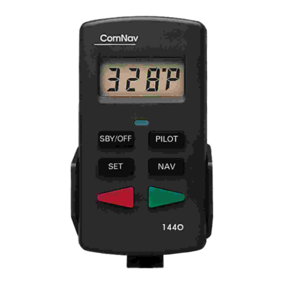
- Page 44 LOCATING THE “FLUSH KEY” 1440 shown in the Pilot mode and steering a heading of 359 degrees The Flush Key, on a 1440 Control Head, is located immediately below the digital display and is flush with Control surface to prevent accidental button pushes.
- Page 45 1440 SET-UP ROUTINE (see page 51 for 1460 set-up routine) The 1440 must be OFF before you begin the Press and hold the Flush Set-up Routine. The first part of this routine Key (see below). Press and hold can be done at the dock. If you have a...
- Page 46 The display will show [HO S] The display will next show [HO P] (Hard Over (Hard Over to Starboard). to Port). Turn the steering wheel fully to the left. Press the Set Key. 2. Turn the steering wheel fully to the right.
- Page 47 CAUTION an existing mechanical or hydraulic drive unit, you must now bleed and/or time your pump. In the next step, the 1440 will move the Please see the section titled Pump Bleeding steering system through its full range of Instructions.
- Page 48 If the compass is a Fluxgate Compass the Press the Set Key display will show [FLUH]. The Autopilot will next display [turn] (Turn). You must now adjust your compass. Press the Set Key. The Autopilot The Autopilot will next display a message will turn off.
- Page 49 For Fluxgate Compasses Slowly turn the boat in as small a circle as possible. To fully adjust the Fluxgate Compass, it is necessary to take a short trip with your boat. It must take at least one minute to complete Put your tools and other magnetic objects in the turn.
- Page 50 For Magnetic Compasses For Fluxgate Compasses Autopilot will display [nort] (north) If you have a magnetic compass after successful calibration of the fluxgate the Autopilot will display [nort] (North). compass (#10 in Set-up Routine). As accurately as possible, point your vessel to magnetic North and press the As accurately as possible, point your Set Key.
- Page 51 1460 SET-UP ROUTINE 1460 MUST BE OFF BEFORE YOU BEGIN THE Set-up Routine. The first part of this Press and hold the Flush Key (see Routine can be done at the dock. If you have page 32). Press and hold the Pilot Key a Fluxgate Compass, you will later repeat the until the display shows [FrST] and then first part away from the dock.
- Page 52 The display will show [HO S] The display will next show [HO P} (Hard Over to Starboard). (Hard Over to Port). Turn the steering wheel fully to the Turn the steering wheel fully to the right. Press the Set Key. left.
- Page 53 IMPORTANT The steering gear will move from side to side. Move the steering wheel to the As the Autopilot tests the drive system the center position. display will show [d’tSt]. As the Autopilot checks the rudder the display will show [r’tSt]. The Output marks at the top of the display will show the direction of rudder movement.
- Page 54 Press the Set Key. If the compass is a Fluxgate Compass the display will show [FLUH]. The Autopilot will next display [tUrN] (Turn). You must now adjust your compass. The Autopilot will next display a message about the compass type. If you have a magnetic compass the display will show [nAG] (magnetic).
- Page 55 For Fluxgate Compasses Slowly turn the boat in as small a circle as possible. To fully adjust the Fluxgate Compass, it is necessary to take a short trip with your boat. It must take at least one minute to complete the turn.
- Page 56 For Magnetic Compasses For Fluxgate Compass If you have a magnetic compass the If you have a fluxgate compass, the Autopilot will display [nort] (North). Autopilot will display [nort] (North) after successful calibration of the fluxgate compass (#10 in Set-up Routine). As accurately as possible, point your vessel to magnetic North and press the Set Key.
- Page 57 Pump Bleeding Instructions The manufacturer of your system may Bleed your manual steering system provide these items when you purchase according manufacturer's a bleeding kit for your system. If you instructions. When you have completed have a helper, have them watch the oil the bleeding, leave the equipment for level in the highest reservoir and refill it the bleeding procedure attached to your...
- Page 58 Bleeding cylinder, rod moving left Bleeding cylinder, rod moving right. P/N 83468 V1.2...
- Page 59 **** IMPORTANT **** If you have installed a ComNav Marine reversing motor pump, a constant running pump or an engine driven pump, there are several checks that must be done during the first several weeks of usage in order to prevent poor or dangerous steering performance.
- Page 60 This page intentionally blank P/N 83468 V1.2...
-
Page 61: Piloting With The 1440 Or 1460 Autopilot
The COMNAV Autopilot has a very wide versions and last, vessel heading followed by range of steering control settings. There are: a “P”. You are now piloting with the 1440 or 1460. To get manual command back, press • Four: Rudder Response settings. -
Page 62: Setting Slow Speed Rudder Response
Bring your boat onto a course. performance. The pilot may move back and forth across the desired course line. Turn ON the 1440 or 1460 Autopilot. To turn on the Autopilot, press the Pilot Key. The This movement occurs when your rudder... -
Page 63: Turns And Changing Course
If this new setting is still not suitable, While you are travelling slowly, it is a good repeat the instructions above. Continue this time to practice using your COMNAV process until your vessel is steering well. Autopilot. The vessel may also gradually fall off the... - Page 64 Pressing the Red or Green Key in S Small Course Change TANDBY switches the Autopilot to Power Steer Mode. The display will have a degree symbol To make a one degree course change to the in the top right corner [xxx º]. You can now right, briefly press and release the Green Key.
-
Page 65: Setting Fast Speed Rudder & Counter-Rudder Response
Counter-Rudder heading is correct, press the Pilot Key. The sensitivity: 1440 or 1460 will steer along the new course. Press the Set Key. The display will show 4. Press the SBY/OFF Key. The Autopilot will [FASt] for five seconds. -
Page 66: Fast Speed Turns And Course Changes
To increase Rudder sensitivity: Fast Speed Turns and Course Press the Set Key. The display will show Changes [FASt] for five seconds. During this five second interval, press the Set Key again and Your vessel will respond more quickly to a the Autopilot will display the Rudder sensitivity Red or Green Key press than it did in the setting. - Page 67 CORRECT VESSEL RESPONSE DURING A COURSE CHANGE P/N 83468 V1.2...
-
Page 68: Adjusting Your Digital Rudder Angle Indicator (Rai)
Angle Indicator (RAI) Many vessels always need the rudder positioned to the right or left a small amount. The 1440 & 1460 also provide an electronic This slightly offset rudder position is needed Rudder Angle Indicator. to correct for the turning effect of a single propeller. -
Page 69: Using Your Navigation Interface
For a complete listing of Navigation new bearing. The 1440 or 1460 will bring Sentences used by ComNav see page your boat onto the new course. It will steer towards the Waypoint using the information from the Nav device and the compass. -
Page 70: The Navigation Interface
The Navigation Interface Because of this, the COMNAV Autopilot lets you change the way it interprets the direction of cross track error. In N , press the Your COMNAV Autopilot will receive Flush Key. The display will show either [---‘n] information sent to it from a navigation device (normal) or [---r] (reversed). - Page 71 Be aware that not all LORANS, GPS, or plotters conform to the NMEA standard. Statements that a GPS, LORAN, or plotter provide navigation data may mean that the data is provided only in the manufacturer’s own language. If you are purchasing a LORAN, GPS or plotter, make sure that it sends out at least one of the listed sentences.
- Page 72 NAV Mode display shows the following for the type of sentence it is utilizing for navigating a course. Crosstrack quality The first 2 digits (XXx) denotes the source of the cross track data, if any and are used as a relative priority.
- Page 73 1440 and 1460 Operation Commands COMMAND ACTION RESULT Steer by compass 1440/1460 is off or in S Boat will settle on course. TANDBY Display will show [xxxP]. Point bow and press Pilot x x x P Key. Immediately upon pressing the...
- Page 74 Press Green Key to increase or Red Key to decrease brightness. Change from compass In P , press The 1440 or 1460 will constantly OWER TEER display to permanent rudder the Set Key. display the rudder angle while in angle display.
-
Page 75: Adjustment Commands
Adjustment Commands COMMAND ACTION RESULT Autopilot will steer with a “harder” Rudder sensitivity: increase or N ILOT turn to correct course deviations, Press Set Key twice. causing a shorter correction, but more overshoot of the intended Press Green Key. course. Changes will only affect the current speed (fast or slow) sensitivity setting. -
Page 76: User Codes For The 1440 & 1460
HECK Cancel the alarm using the Pilot Key. The message will reappear whenever the 1440 or 1460 is in Pilot Mode. The digital and analog RAI will not work. The battery voltage is more than 40 volts. If this problem is not fixed, the Processor could be damaged. - Page 77 : The Processor and the Processor space for heat sources. HECK Should the temperature rise still higher, the 1440 or 1460 will turn off the steering outputs. When the temperature falls, the steering outputs will turn back on. We recommend that you have the Autopilot serviced by a COMNAV dealer before it is used again.
- Page 78 (digit) (digit)* EPROM Error. This indicates a failure in the Processor. Take the PRON Autopilot to a COMNAV service center. Ram Error. This indicates a failure in the Processor. Take the Autopilot to a COMNAV service center Occurs during Set up Routine. See page 45 or 51.
-
Page 79: Problems Without An Error Code
The random occurrence of this problem is possible but unlikely. If this problem occurs twice, your Autopilot may need servicing. Contact your COMNAV dealer. The Control Head display The 1440 or 1460 Control Head may be disconnected. For goes blank, Autopilot... -
Page 80: Appendix A
APPENDIX A Connections to 4 and 5 Wire Motors P/N 83468 V1.2... - Page 81 APPENDIX A Connections to 4 and 5 Wire Motors (using a clutch or lockup valve) Rated for 3 amps continously/5 amps intermittently P/N 83468 V1.2...
-
Page 82: Appendix B
APPENDIX B Connections to Solenoid Valves FUSE OR BREAKER SOLENOID VALVE 1 2V, 24V, 32V DC 1 2v, 24V, 32V DC BATTERY JOG LEVER ACTIVE IN ALL MODES DISABLED BY SW ITCHING THE CIRCUIT BREAKER JOG LEVER (OPTIONAL) COMMON POSITIVE SOLENOID HOOKUP P/N 83468 V1.2... -
Page 83: Connecting A Second Location Or Second Station Options
1440 Control head at several locations. If you chose this method, it is important to note that only one 1440 Control Head can be connected at any given time. You are in fact only moving your Control Head from one location to another. -
Page 84: Second Station Kit
To connect the cable, first loosen off the right-hand cap on the COMNAV Processor Box and remove the “knock-out” at the top of the cap by using a 9/32 inch (7mm) drill. Once the “knock-out” has been removed, install the cable gland and the cable. Next connect the individual wires on the second location cable to the middle terminal strip, paralleling the existing main receptacle wiring (Cable 1). - Page 85 Operation The Second Station is identical in operation to the Main Station as described in “Piloting with the 1440 or 1460 Autopilot”. Only one of the controls can operate the autopilot at any given time. The unit that is non-active will have a continuously flashing LCD display and the active control will have a steady display.
-
Page 86: Appendix D
APPENDIX D Connecting a Rudder Angle Indicator Right-hand side showing optional RAI connection. The cable gland for a rudder angle indicator is in your Accessory Bag. We do not supply a cable for this installation but recommend a #22 gauge, two conductor cable that is round in order to make a water- tight seal. -
Page 87: Appendix E
J5 and the other wire (return) connects to pin 2 of terminal strip J5. Terminal strip J5 is located in the lower right side of the 1440 Processor circuit board (see above). The two pin connector required for connecting the heading output is included in your accessory kit. - Page 88 This page is intentionally blank. P/N 83468 V1.2...
-
Page 89: Limited Warranty Agreement
Authorized ComNav Dealer; and the Limited Warranty Registration Card has been returned to ComNav within 14 days of the date of purchase of the Equipment by the Purchaser with Part I thereof having been completed by the Purchaser, and with the Extended Limited Warranty Card having been completed and signed by an authorized ComNav Dealer and returned to ComNav within 14 days of that inspection;... - Page 90 Purchaser. Notices sent by mail will be deemed to be received by ComNav on the seventh (7th) day first following the date of posting in North America and on the tenth (10th) day next following the date of posting anywhere else in the world.
- Page 91 HAVE OTHERS WHICH VARY FROM STATE/JURISDICTION TO STATE/JURISDICTION. This Agreement is a legal contract between you (the "Purchaser") and ComNav. By retaining the Equipment for more than thirty (30) days and/or installing and/or using the Equipment, the Purchaser agrees to be bound by the terms of this Agreement.
-
Page 92: Ce Compliance
Immunity to conducted radio frequencies Annex A, Section A.6: Immunity to radiated interference Test results and a declaration of conformity are on file at the ComNav plant; ComNav Marine Ltd #15 - 13511 Crestwood Place Richmond, BC, V6V 2G1, Canada June 28, 1999 P/N 83468 V1.2...
Need help?
Do you have a question about the 1440 and is the answer not in the manual?
Questions and answers