
Related Manuals for Dell EMC DSS8440


Summary of Contents for Dell EMC DSS8440
- Page 1 Dell EMC DSS8440 Installation and Service Manual Regulatory Model: B21S Series Regulatory Type: B21S001...
- Page 2 Notes, cautions, and warnings NOTE: A NOTE indicates important information that helps you make better use of your product. CAUTION: A CAUTION indicates either potential damage to hardware or loss of data and tells you how to avoid the problem. WARNING: A WARNING indicates a potential for property damage, personal injury, or death.
-
Page 3: Table Of Contents
Contents 1 About this document............................7 2 Dell EMC DSS8440 system overview......................8 DSS8440 system feature overview..........................9 Front view of the system............................9 Rear view of the system............................10 3 Technical specifications..........................11 Chassis dimensions................................12 Chassis weight.................................. 12 Processor specifications..............................12 PSU specifications................................13... - Page 4 Embedded system management..........................40 Boot Manager.................................. 40 Viewing Boot Manager..............................40 Boot Manager main menu............................41 One-shot UEFI boot menu............................41 System Utilities................................41 PXE boot....................................41 6 Installing and removing system components....................42 Safety instructions................................42 Before working inside your system..........................42 After working inside your system...........................42 Recommended tools................................42 System cover..................................43...
- Page 5 Installing the fan cage..............................92 Handle....................................93 Removing the handle..............................93 Installing the handle..............................94 Slide rail installation................................95 7 Cable Routing.............................100 Dell EMC DSS8440 cable instruction........................... 101 3M cable Installation-Config A left..........................103 3M cable Installation-Config A right..........................104 Fan cable assembly to fan bracket ..........................105 Contents...
- Page 6 Power cable2 Riser-PDB assembly to PDB.........................135 Power cable2 Riser-PDB assembly to Riser........................136 8 Jumpers and connectors..........................137 System Board Connectors............................138 System board jumpers settings............................ 140 Disabling forgotten password............................140 9 Getting help..............................141 Contacting Dell EMC..............................141 Documentation feedback............................... 141 Contents...
-
Page 7: About This Document
About this document This document provides an overview about the system, information on installing and replacing components, technical specifications, diagnostic tools, and guidelines to be followed while installing certain components. About this document... -
Page 8: Dell Emc Dss8440 System Overview
Dell EMC DSS8440 system overview This chapter briefly describes the main features of the Dell EMC DSS8440 system. The chapter includes figures of the products, a list of the server system features, and diagrams showing the location of the components and connections on the server systems. -
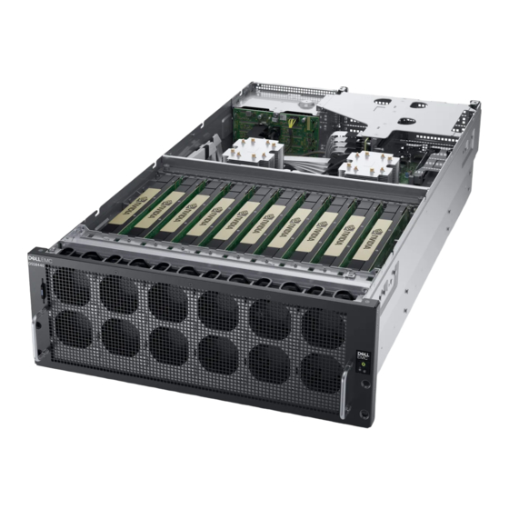
Page 9: Dss8440 System Feature Overview
DSS8440 system feature overview The DSS8440 is a 4U PCIe Accelerator Server by PCIe Switch Board(PSB) with PCIe downstream up to 10x general-purpose double width graphics processing unit (GPGPU), 8x NVMe, 4x (center) + 4x (right, optional) rear-PCIe slots and upstream the 14G leveraged PowerEdge C4140. -
Page 10: Rear View Of The System
System identification button Rear view of the system Figure 5. Rear view of the system Slots-4, 5, 14, 15 Slots-[19..16] Drive-[0..9] Slot-1 Slot-3 Power-Jack RJ45 DB15 2x USB-3.0 2x RJ45 + 2xSFP+ Power Supply 1 to 4 Dell EMC DSS8440 system overview... -
Page 11: Technical Specifications
Technical specifications The technical and environmental specifications of your system are outlined in this section. Topics: • Chassis dimensions • Chassis weight • Processor specifications • PSU specifications • Cooling fans specifications • System battery specifications • Expansion card riser specifications •... -
Page 12: Chassis Dimensions
Maximum weight (with all drives) DSS8440 (2 CPU/ 10 GPU/ 10 HDD/ 1 H730P+/ 1 CX5) 46.3 Kg (102.07 lb) Processor specifications TheDell EMC DSS8440 system supports two Intel Xeon Scalable processors with up to 20 cores per processor. Technical specifications... -
Page 13: Psu Specifications
NOTE: Ensure that both the processors are populated and both are of the same type or model. PSU specifications The system supports up to four redundant AC power supply units (PSUs). Table 3. PSU specifications Functions 2400W Power supply Input Input voltage range AC input : 200Vac~240Vac @ High line : 2400W Frequency... -
Page 14: Cooling Fans Specifications
The Dell EMC DSS8440 system supports CR 2032 3.0-V lithium coin cell system battery. Expansion card riser specifications The Dell EMC DSS8440 system supports up to 10 x Dual Width Full Length PCIe slots and rear I/O 8 x Full Height Half Length PCIe slots. Memory specifications Table 4. -
Page 15: Vga Port Specifications
Dell EMC DSS8440 system supports one 15 pin VGA ports available through the back panel. LOM port specifications Dell EMC DSS8440 system supports two 10GbE SFP+ ports and two 1GbE RJ-45 ports available through the back panel. Environmental specifications The following details define the system level operating and non-operating environmental limits. -
Page 16: Nic Indicator Codes
Icon Indicator, button, Description or connector NOTE: On APCI-compliant operating system, turning off the system using power button causes the system to perform a graceful shutdown before power to the system is turned off. Health indicator Indicates the health of the system. •... -
Page 17: Power Supply Unit Indicator Codes
Table 9. NIC indicators Convention Status Condition Link and activity indicators are off. The NIC is not connected to the network. Link indicator is green. The NIC is connected to a valid network at its maximum port speed (1 Gbps or 10 Gbps). Link indicator is amber. - Page 18 Convention Power indicator Condition pattern Flashing green and When hot-adding a PSU, the PSU handle flashes green five times at 4 Hz rate and turns turns off. off. This indicates a PSU mismatch with respect to efficiency, feature set, health status, and supported voltage.
-
Page 19: Initial System Setup And Configuration
The Integrated Dell Remote Access Controller (iDRAC) is designed to make system administrators more productive and improve the overall availability of Dell EMC systems. iDRAC alerts administrators to system issues, helps them perform remote system management, and reduces the need for physical access to the system. -
Page 20: Pre-Operating System Management Applications
Options to manage the pre-operating system applications Your system has the following options to manage the pre-operating system applications: • System Setup • Dell EMC Lifecycle Controller • Boot Manager • Preboot Execution Environment (PXE) System Setup By using the System Setup screen, you can configure the BIOS settings, iDRAC settings and device settings of your system. -
Page 21: System Bios
Option Description The iDRAC settings utility is an interface to set up and configure the iDRAC parameters by using UEFI (Unified Extensible Firmware Interface). You can enable or disable various iDRAC parameters by using the iDRAC settings utility. Device Settings Enables you to configure device settings. - Page 22 Option Description System Profile Provides options to change the processor power management settings, and memory frequency. Settings System Security Provides options to configure the system security settings, such as system password, setup password, Trusted Platform Module (TPM) security, and UEFI secure boot. It also manages the power button on the system. Redundant OS Provides the options to configure the Redundant OS settings.
- Page 23 Option Description UEFI Compliance Specifies the UEFI compliance level of the system firmware. Version Memory Settings You can use the Memory Settings screen to view all the memory settings and enable or disable specific memory functions, such as system memory testing and node interleaving. Viewing Memory Settings To view the Memory Settings screen, perform the following steps: Power on, or restart your system.
- Page 24 Option Description Node Interleaving Specifies if Non-Uniform Memory Architecture (NUMA) is supported. If this field is set to Enabled, memory interleaving is supported if a symmetric memory configuration is installed. If this field is set to Disabled, the system supports NUMA (asymmetric) memory configurations. This option is set to Disabled by default. Snoop Mode Specifies the Snoop Mode options.
- Page 25 Option Description Software Enables or disables the software prefetcher. This option is set to Enabled by default. Prefetcher DCU Streamer Enables or disables the Data Cache Unit (DCU) streamer prefetcher. This option is set to Enabled by default. Prefetcher DCU IP Prefetcher Enables or disables the Data Cache Unit (DCU) IP prefetcher.
- Page 26 SATA Settings You can use the SATA Settings screen to view the settings of SATA devices and enable SATA and PCIe NVMe RAID mode on your system. Viewing SATA Settings To view the SATA Settings screen, perform the following steps: Power on, or restart your system.
- Page 27 – Support for drive partitions larger than 2 TB. – Enhanced security (e.g., UEFI Secure Boot). – Faster boot time. NOTE: You must use only the UEFI boot mode in order to boot from NVMe drives. • BIOS: The BIOS Boot Mode is the legacy boot mode. It is maintained for backward compatibility. Viewing Boot Settings To view the Boot Settings screen, perform the following steps: Power on, or restart your system.
- Page 28 Network Settings You can use the Network Settings screen to modify UEFI PXE, iSCSI, and HTTP boot settings. The network settings option is available only in the UEFI mode. NOTE: BIOS does not control network settings in the BIOS mode. For the BIOS boot mode, the optional Boot ROM of the network controllers handles the network settings.
- Page 29 UEFI iSCSI Settings You can use the iSCSI Settings screen to modify iSCSI device settings. The iSCSI Settings option is available only in the UEFI boot mode. BIOS does not control network settings in the BIOS boot mode. For the BIOS boot mode, the option ROM of the network controller handles the network settings.
- Page 30 Integrated Devices details The Integrated Devices screen details are explained as follows: Option Description User Accessible Configures the user accessible USB ports. Selecting Only Back Ports On disables the front USB ports; selecting USB Ports All Ports Off disables all front and back USB ports. The USB keyboard and mouse still function in certain USB ports during the boot process, depending on the selection.
- Page 31 Option Description Internal SD Primary When Redundancy is set to Disabled, either one of the SD card can be selected to present itself as mass storage Card device by setting it to be primary card. By default, the primary SD card is selected to be SD Card 1. If SD Card 1 is not present, then the controller selects SD Card 2 to be the primary SD card.
- Page 32 Serial Communication You can use the Serial Communication screen to view the properties of the serial communication port. Viewing Serial Communication To view the Serial Communication screen, perform the following steps: Power on, or restart your system. Press F2 immediately after you see the following message: F2 = System Setup NOTE: If your operating system begins to load before you press F2, wait for the system to finish booting, and then...
- Page 33 Option Description Redirection After Enables or disables the BIOS console redirection when the operating system is loaded. This option is set to Boot Enabled by default. System Profile Settings You can use the System Profile Settings screen to view the properties of the serial communication port. Viewing System Profile Settings To view the System Profile Settings screen, perform the following steps: Power on, or restart your system.
- Page 34 Option Description Memory Refresh Sets the memory refresh rate to either 1x or 2x. This option is set to 1x by default. Rate Uncore Frequency Enables you to select the Processor Uncore Frequency option.Dynamic mode enables the processor to optimize power resources across cores and uncores during runtime.
- Page 35 Option Description Intel(R) AES-NI Improves the speed of applications by performing encryption and decryption by using the Advanced Encryption Standard Instruction Set (AES-NI). This option is set to Enabled by default. System Password Enables you to set the system password. This option is set to Enabled by default and is read-only if the password jumper is not installed in the system.
- Page 36 Option Description If the current mode is set to Deployed Mode, the available options are User Mode and Deployed Mode. If the current mode is set to User Mode, the available options are User Mode, Audit Mode, and Deployed Mode. Options Description User Mode...
- Page 37 Reenter the system password, and click OK. In the Setup Password field, type your setup password and press Enter or Tab. A message prompts you to reenter the setup password. Reenter the setup password, and click OK. Press Esc to return to the System BIOS screen. Press Esc again. A message prompts you to save the changes.
- Page 38 If you do not type the correct password in three attempts, the system displays the following message: Invalid Password! Number of unsuccessful password attempts: <x> System Halted! Must power down. Password Invalid. Number of unsuccessful password attempts: <x> Maximum number of password attempts exceeded.System halted.
- Page 39 Option Description NOTE: BIOS will disable the device in hardware, so it cannot be accessed by the OS. Redundant OS Boot NOTE: This option is disabled if Redundant OS Location is set to None or if Redundant OS State is set to Hidden.
-
Page 40: Idrac Settings Utility
iDRAC Settings utility The iDRAC settings utility is an interface to set up and configure the iDRAC parameters by using UEFI. You can enable or disable various iDRAC parameters by using the iDRAC settings utility. NOTE: Accessing some of the features on the iDRAC settings utility needs the iDRAC Enterprise License upgrade. For more information about using iDRAC, see Dell Integrated Dell Remote Access Controller User's Guide at Dell.com/poweredgemanuals. -
Page 41: Boot Manager Main Menu
Boot Manager main menu Menu item Description Continue Normal The system attempts to boot to devices starting with the first item in the boot order. If the boot attempt fails, the Boot system continues with the next item in the boot order until the boot is successful or no more boot options are found. -
Page 42: Installing And Removing System Components
Installing and removing system components Safety instructions WARNING: Whenever you need to lift the system, get others to assist you. To avoid injury, do not attempt to lift the system by yourself. WARNING: Opening or removing the system cover while the system is powered on may expose you to a risk of electric shock. CAUTION: Do not operate the system without the cover for a duration exceeding five minutes. -
Page 43: System Cover
System cover Removing the system cover Prerequisites Follow the safety guidelines listed in Safety instructions. Power off the system and all attached peripherals. Disconnect the system from the electrical outlet and disconnect the peripherals. Steps Loosen and remove the captive screw on the system cover Slid the system cover backwards and lift the cover from the system. -
Page 44: Front Bezel
NOTE: The captive screw must be tightened with a screwdriver after the top chassis is closed. Figure 10. Installing the system cover Next steps Reconnect the peripherals, and connect the system to the electrical outlet. Power on the system and all attached peripherals. Front bezel Removing the front bezel Prerequisites... -
Page 45: Installing The Front Bezel
Figure 11. Removing the screws Remove the front bezel from the fan cage. Figure 12. Removing the front bezel Installing the front bezel Prerequisite Follow the safety guidelines listed in Safety instructions. Steps Place the front bezel onto the chassis and slide the front bezel into place. Installing and removing system components... -
Page 46: Air Shroud
Figure 13. Installing the front bezel Tighten the screws to secure the front bezel to the fan cage. Next steps Install the system cover Follow the procedure listed in After working inside your system Air shroud Removing the air shroud Prerequisites CAUTION: Never operate your system with the air shroud removed. -
Page 47: Installing The Air Shroud
Follow the procedure listed in Before working inside your system. Remove the system cover. Step NOTE: The screws on top of the air shroud are meant to secured the T_standoff. Do not remove the crews when removing the air shroud. Slide the air shroud backward to unlock it from the T_standoff and lift the air shroud out of the system. -
Page 48: Drives
Figure 15. Installing the air shroud Next steps Install the system cover. Follow the procedure listed in After working inside your system Drives Removing a drive carrier and drive Prerequisite Follow the safety guidelines listed in Safety instructions. Steps Remove the drive carrier by pressing the latch to unlock and pull the drive carrier out of the system. Installing and removing system components... -
Page 49: Installing The Drive And Drive Carrier
Figure 16. Removing the drive carrier Remove the four screws securing the drive to the carrier. Remove the drive from the carrier. Figure 17. Removing the drive from the drive carrier Next step Install the drive carrier. Related link Installing the drive and drive carrier Installing the drive and drive carrier Prerequisite Follow the safety guidelines listed in Safety instructions. -
Page 50: Drive Backplane
Figure 18. Install the drive Insert the drive carrier into the chassis, and then push the drive carrier into the place. Figure 19. Installing the drive carrier Next step Follow the procedure listed in After working inside your system Drive backplane Removing the drive backplane Prerequisites Follow the safety guidelines listed in... -
Page 51: Installing The Drive Backplane
Remove the system cover. Remove all the drives.. Disconnect all the cables. Steps Remove the one screw securing the drive backplane to the system. Lift the backplane from the hooks and then pull away from the system. Figure 20. Removing the drive backplane Next step Install the drive backplane Installing the drive backplane... -
Page 52: Power Supply Unit
Next steps Connect all the cables. Install the all drives. Install the top cover. Follow the procedure listed in After working inside your system Power supply unit Removing a power supply unit Prerequisites CAUTION: The power supply is only hot-swappable if you have a redundant system with all power supplies installed. If you only have one power supply installed, before removing or replacing the power supply, you must first take the server out of service, turn off all peripheral devices connected to the system, turn off the system by pressing the power button, and unplug the AC power cord from the system or wall outlet. -
Page 53: Installing A Power Supply Unit
Installing a power supply unit Prerequisites Follow the safety guidelines listed in safety instructions. For systems that support redundant PSU, ensure that all the PSUs are of the same type and have the same maximum output power. NOTE: The maximum output power (shown in watts) is listed on the PSU label. Step Insert the power supply module into the power supply cage and push all the way until it clicks into place. -
Page 54: Installing A Gpu
Steps Remove the screws securing the GPU clamp. Lift the GPU clamp from the system. Figure 24. Removing the GPU clamp Release two captive plungers on the GPU holding bracket and slide sideway to lift it from the system Disconnect power cable from GPU card Lift the GPU card from the system. -
Page 55: Removing A Gpu Support Bracket
Figure 26. Installing the GPU card Insert the GPU clamp into chassis. Secure fixing the GPU clamp by four screws. Figure 27. Installing the GPU clamp Next steps Installing the system cover.. Follow the procedure listed in After working inside your system Removing a GPU support bracket Prerequisites Follow the safety guidelines listed in... -
Page 56: Installing A Gpu Support Bracket
Steps Loosen the two screws securing the GPU support bracket. Remove the GPU support bracket. Figure 28. Removing the GPU support bracket Installing a GPU support bracket Prerequisite Follow the safety guidelines listed in Safety instructions. Steps Install the GPU support bracket into place. Secure the GPU support bracket using two screws. -
Page 57: Removing The Pcie Switch Board
Figure 29. Installing the GPU support bracket Next steps Install the GPU card. Install the system cover. Follow the procedure listed in After working inside your system Removing the PCIe switch board Prerequisites Follow the safety guidelines listed in Safety instructions. - Page 58 Figure 30. Lift up the two levers Lift the PCIe switch board module from the system. Figure 31. Removing the PCIe switch board Remove the fourteen screws securing the PCIe switch board. and loosen the two captive screws. Installing and removing system components...
-
Page 59: Installing The Pcie Switch Board
Figure 32. Remove the screws securing the PCIe switch board Lift the PCIe switch board from the GPU base. Installing the PCIe switch board Prerequisite Follow the safety guidelines listed in Safety instructions. Steps Insert the PCIe switch board into GPU base. Secure fixing the PCIe switch board by fourteen screws and tighten the two captive screws. - Page 60 Figure 34. Insert the two levers Secure fixing the PCIe switch board module by six screws. Figure 35. Installing the PCIe switch board module Next steps Connect all the cables. Install the GPU support bracket Installing and removing system components...
-
Page 61: Removing A Gpu Power Interposer Board
Install the GPU card Install the system cover Follow the procedure listed in After working inside your system Removing a GPU power interposer board Prerequisites Follow the safety guidelines listed in Safety instructions. Follow the procedure listed in Before working inside your system. -
Page 62: Installing A Gpu Power Interposer Board
Installing a GPU power interposer board Prerequisites Follow the safety guidelines listed in Safety instructions. Connect all the cables to the GPU power interposer board Steps Insert the GPU power interposer board into GPU base. Secure fixing the GPU power interposer board by eleven screws. Figure 37. - Page 63 Steps Remove the four screws securing the butterfly module. Disconnect all the cables and release the cable ties. Remove 3M cable start from the bottom as the cable release latch facing the bottom of the butterfly module. Lift the butterfly module from the system. Figure 38.
-
Page 64: Installing The Riser 3 Board And Butterfly Module
Installing the riser 3 board and butterfly module Prerequisite Follow the safety guidelines listed in Safety instructions. Steps Insert the riser 3 board into riser bracket. Secure fixing the both the riser 3 board by eight screws. Figure 40. Installing the riser 3 board Connect all the cables. -
Page 65: Processor And Heat Sink
Figure 41. Installing the butterfly module Next steps Install the system cover Follow the procedure listed in After working inside your system Processor and heat sink Removing the processor and heat sink Prerequisites WARNING: The heat sink may be hot to touch for some time after the system is powered down. Allow the heat sink to cool before removing it. -
Page 66: Installing The Processor
NOTE: It is normal for the heat sink to slip off the blue retention clips when the screws are partially loosened, continue to loosen the screw(s). Pushing both blue retention clips simultaneously, lift the processor and heat sink module (PHM) out of the system. Set the PHM aside with the processor side facing up. -
Page 67: System Memory
b Tighten the second screw completely. Return to the first screw and tighten it completely. If the PHM slips off the blue retention clips when the screws are partially tightened, follow these steps to secure the PHM: Loosen both the heat sink screws completely. Lower the PHM on to the blue retention clips, follow the procedure described in step 2. -
Page 68: Installing A Memory Module
Figure 44. removing a memory module Next step Install a memory module. Installing a memory module Prerequisite Follow the safety guidelines listed in Safety instructions. Steps Locate the appropriate memory module socket. Push the ejectors outward on both ends of the memory module socket. Holding the DIMM by edges insert it into socket tightly. -
Page 69: Riser 2 Module
Figure 45. Installing a memory module Next steps If applicable, Install the air shroud. Install the system cover Follow the procedure listed in After working inside your system Riser 2 module Removing the riser 2 module Prerequisites Follow the safety guidelines listed in Safety instructions. -
Page 70: Installing The Riser 2 Module
Figure 46. Removing the riser 2 module Open the PCIe bracket latch, removing the H730P+ card from the riser 2 module. Figure 47. Removing the H730P+ card Next step Install the riser 2 card. Installing the riser 2 module Prerequisite Follow the safety guidelines listed in Safety instructions. - Page 71 Figure 48. Open the PCIe bracket latch Install the H730P+ card to the riser2 module. Figure 49. Installing the H730P+ card Close PCIe bracket latch. Press the riser2 module -edge down until the card is fully seated. Align the riser2 module connector with the card connector on the system board and push the riser2 module wards the connector to seat it firmly.
-
Page 72: Riser 1 Module
Figure 50. Installing the riser 2 module Next steps Install the butterfly module. Install the top cover. Follow the procedure listed in After working inside your system Riser 1 module Removing the riser 1 module Prerequisites Follow the safety guidelines listed in Safety instructions. -
Page 73: Installing The Riser 1 Module
Figure 51. Removing the riser 1 module Next step Install the riser 1 card Installing the riser 1 module Prerequisite Follow the safety guidelines listed in Safety instructions. Steps Align the riser1 module connector with the card connector on the system board and push the riser1 module wards the connector to seat it firmly. -
Page 74: Network Daughter Card
Figure 52. Installing the riser 1 module Next steps Install the butterfly module. Install the top cover. Follow the procedure listed in After working inside your system Network daughter card Removing the network daughter card Prerequisites Follow the safety guidelines listed in Safety instructions. -
Page 75: Installing The Network Daughter Card
Figure 53. Removing the network daughter card Installing the network daughter card Prerequisite Follow the procedure listed in Before working inside your system Steps Orient the NDC so that the Ethernet connectors fit through the slot in the chassis. Align the captive screws at the back-end of the card with the screw holes on the system board. Press the touch points on the card until the card connector is firmly seated on the system board connector. -
Page 76: System Board Tray Module
Figure 54. Installing the network daughter card System board tray module Removing the system board tray module Prerequisites Follow the safety guidelines listed in Safety instructions. Follow the procedure listed in Before working inside your system. Remove the following: Remove the system cover. Remove the air shroud. - Page 77 Figure 55. Loosen one screw Slide the system board tray to make sure the it's not secured by the T standoff. Lift the system board tray module out of the chassis. Figure 56. Removing the system board tray module Next step Install the system board tray module Installing and removing system components...
-
Page 78: Installing The System Board Tray Module
Installing the system board tray module Prerequisite Follow the safety guidelines listed in Safety instructions. Steps Align the location pin to install system board tray module. Slide the system board tray to T standoff and make sure the T standoff can fix system board tray exactly. Figure 57. -
Page 79: System Board And Power Interposer Board
Next steps Reconnect all cables to the system board tray module. Install the following: Processor and heat sink Memory Riser 1 module Riser 2 module Butterfly module GPU support bracket GPU card Air shroud System cover Follow the procedure listed in After working inside your system System board and power interposer board Removing the system board and power interposer board... -
Page 80: Installing The System Board And Power Interposer Board
Figure 59. Removing the system board and power interposer board Lift the power interposer board from the system board. Figure 60. Removing the power interposer board Next step Install the system board and power interposer board. Installing the system board and power interposer board Prerequisite Follow the safety guidelines listed in Safety... - Page 81 Steps Install the power interposer board to the system board. Figure 61. Installing the power interposer board Install system board and power interposer board to system board tray. Tighten the one original screw to secure the system board handle to the system board. Tighten the eighteen screws to secure the system board and power interposer board to the system board tray.
-
Page 82: Backup Battery
Follow the procedure listed in After working inside your system Backup battery Replacing the backup battery Prerequisites CAUTION: Dispose the battery according to local ordinance. NOTE: You will need to run the BIOS Setup to restore the configuration settings to the RTC. Follow the safety guidelines listed in Safety instructions. -
Page 83: Power Distribution Board
Next steps Install the butterfly module. Install the top cover. Follow the procedure listed in After working inside your system. While booting, press F2 to enter the System Setup and ensure that the battery is operating properly. Enter the correct time and date in the System Setup Time and Date fields. Exit the System Setup. -
Page 84: Installing The Power Distribution Board
Next step Install the power distribution board. Installing the power distribution board Prerequisite Follow the safety guidelines listed in Safety instructions. Steps Install the power distribution board to the system chassis. Tighten the eight screws to secure the power distribution board to the system chassis. Figure 66. -
Page 85: Psb Power Interposer Board
PSB power interposer board Removing the PSB power interposer board Prerequisites Follow the safety guidelines listed in Safety instructions. Follow the procedure listed in Before working inside your system. Remove the following: Remove the system cover. Remove the air shroud. Remove the GPU card. -
Page 86: Installing The Psb Power Interposer Board
Installing the PSB power interposer board Prerequisites Follow the safety guidelines listed in Safety instructions. Connect all cables to the PSB power interposer board Steps Install the PSB power interposer board to the system. Tighten the four screws to secure the PSB power interposer board to the system. Figure 68. -
Page 87: Front Control Module
Front control module Removing the front control module Prerequisites Follow the safety guidelines listed in Safety instructions. Follow the procedure listed in Before working inside your system. Remove the following: System cover. Front bezel Butterfly module Steps Disconnect front control module cable from system board. Loosen the two screws. -
Page 88: Fan Louvers
Connect the front control module cable to the system board and ensure that the cable routing is correct. Figure 70. Installing the front control module Next steps Install the Butterfly module,front bezel,System cover. Follow the procedure listed in After working inside your system. Fan louvers Removing the fan louvers Prerequisites... -
Page 89: Installing The Fan Louvers
Figure 71. Removing the fan louvers Installing the fan louvers Prerequisite Follow the safety guidelines listed in Safety instructions. Steps Locate the corresponding hole on the fan cage. Installing and removing system components... - Page 90 Figure 72. Fan louver hook position Hook the fan louver to the fan cage assembly. Installing and removing system components...
-
Page 91: Cooling Fans
Next steps Install the following: GPU clamp and GPU card Air shroud System cover Follow the procedure listed in After working inside your system Cooling fans Replacing a cooling fan Prerequisites CAUTION: Cooling fans are not hot swappable. Follow the safety guidelines listed in Safety instructions. -
Page 92: Fan Cage
Fan cage Removing the fan cage Prerequisites Follow the safety guidelines listed in Safety instructions. Follow the procedure listed in Before working inside your system. Remove the system cover. Remove the PCIe switch board module. Remove the air shroud. Remove the GPU support bracket. Remove the system board tray module. -
Page 93: Handle
Steps Install the fan cable to the fan cage. Install the fan cage to the power distribution board. Tighten the sixteen screws to secure the fan cage to the system chassis. Figure 75. Installing the fan cage Next steps Connect the fan cable to the PSB power interposer board. Install the following: Install the front control module. -
Page 94: Installing The Handle
Figure 76. Removing the handle Next steps Install the handle. Follow the procedure listed in After working inside your system Installing the handle Prerequisite Follow the safety guidelines listed in Safety instructions. Steps Install the handle into the chassis. Lock the handle by plunger. Installing and removing system components... -
Page 95: Slide Rail Installation
NOTE: Please install the four handles in chassis simultaneously for lifting the system. Figure 77. Installing the handle Next step Follow the procedure listed in After working inside your system Slide rail installation Prerequisites Follow the safety guidelines listed in Safety instructions. Follow the procedure listed in Before working inside your system. - Page 96 Figure 78. Removal of the inner member Install the inner member into the chassis. Installing and removing system components...
- Page 97 Figure 79. Installation of inner member into the chassis Screw the outer member and bracket into the racket. Installing and removing system components...
- Page 98 Figure 80. Installation of outer member into the rack Insert the chassis to complete the installation. Pull the middle rail fully extended in lock position, ensure ball bearing retainer is located at the front of the middle rail. b Insert the chassis into middle-outer rails. When hit a stop, please push the release tab on middle rail.
- Page 99 Figure 81. Completion of installation CAUTION: Verify ball bearing retainer is locked forward. Next step Follow the procedure listed in After working inside your system. Installing and removing system components...
-
Page 100: Cable Routing
Cable Routing Figure 82. Cable Routing Cable Routing... -
Page 101: Dell Emc Dss8440 Cable Instruction
Topics: • Dell EMC DSS8440 cable instruction • 3M cable Installation-Config A left • 3M cable Installation-Config A right • Fan cable assembly to fan bracket • Fan cable MB-PDB assembly to MB • Fan cable MB-PDB assembly to PDB •... - Page 102 SAS-HD-cable H730P+ <-> storage- drive backplane OCu-Link-to-mini SAS- C4140 <-> storage-drive HD-Cable backplane SlimLine cable SlimLine left PSB <-> DSS8440, configuration riser-3A, storage-drive BP SlimLine right PSB <-> DSS8440, riser-3A, storage-drive BP SlimLine Slot-4 PSB <-> riser-3A SlimLine Slot-5 PSB <->...
-
Page 103: Cable Installation-Config A Left
3M cable Installation-Config A left Figure 83. 3M cable Installation-Config A left Cable Routing... -
Page 104: Cable Installation-Config A Right
3M cable Installation-Config A right Figure 84. 3M cable Installation-Config A right Cable Routing... -
Page 105: Fan Cable Assembly To Fan Bracket
Fan cable assembly to fan bracket Figure 85. Fan cable assembly to fan bracket Cable Routing... - Page 106 Figure 86. Fan cable assembly to fan bracket Figure 87. Fan cable assembly to fan bracket Cable Routing...
- Page 107 Figure 88. Fan cable assembly to fan bracket Cable Routing...
- Page 108 Figure 89. Fan cable assembly to fan bracket Figure 90. Fan cable assembly to fan bracket Cable Routing...
- Page 109 Figure 91. Fan cable assembly to fan bracket Cable Routing...
-
Page 110: Fan Cable Mb-Pdb Assembly To Mb
Fan cable MB-PDB assembly to MB Figure 92. Fan cable MB-PDB assembly to MB Cable Routing... -
Page 111: Fan Cable Mb-Pdb Assembly To Pdb
Fan cable MB-PDB assembly to PDB Figure 93. Fan cable MB-PDB assembly to PDB Figure 94. Fan cable MB-PDB assembly to PDB Cable Routing... -
Page 112: Front Control Cable Assembly Control Board To Mb
Front control cable assembly control board to MB Figure 95. Front control cable assembly control board to MB Figure 96. Front control cable assembly control board to MB Cable Routing... -
Page 113: Gpu Power Cable Assembly Gpu Card To Psb
Figure 97. Front control cable assembly control board to MB GPU power cable assembly GPU card to PSB Figure 98. GPU power cable assembly GPU card to PSB Cable Routing... -
Page 114: Idc Cable Mb-Pdb Assembly To Pdb
IDC cable MB-PDB assembly to PDB Figure 99. IDC cable MB-PDB assembly to PDB Cable Routing... -
Page 115: Idc Cable Mb-Pdb Assembly To Mb
IDC cable MB-PDB assembly to MB Figure 100. IDC cable (MB-PDB) assembly to MB Cable Routing... -
Page 116: Idc Cable Pdb-Pib Assembly To Pib
IDC cable PDB-PIB assembly to PIB Figure 101. IDC cable PDB-PIB assembly to PIB Cable Routing... -
Page 117: Idc Cable Pib-Pdb Assembly To Pdb
IDC cable PIB-PDB assembly to PDB Figure 102. IDC cable PIB-PDB assembly to PDB Cable Routing... -
Page 118: Idc Cable Riser1-Pdb Assembly To Pdb
IDC cable Riser1-PDB assembly to PDB Figure 103. IDC cable Riser1-PDB assembly to PDB Cable Routing... -
Page 119: Idc Cable Riser1-Pdb Assembly To Riser Board1
IDC cable Riser1-PDB assembly to riser board1 Figure 104. IDC cable Riser1-PDB assembly to riser board1 Cable Routing... -
Page 120: Idc Cable Pib-Pdb Assembly To Pdb
IDC cable PIB-PDB assembly to PDB Figure 105. IDC cable Riser2-PDB assembly to PDB Cable Routing... -
Page 121: Idc Cable Riser 2- Pdb Assembly To Riser Board 2
IDC cable Riser 2- PDB assembly to riser board 2 Figure 106. IDC cable (Riser 2- PDB) assembly to riser board 2 Cable Routing... -
Page 122: Mini Sas Hd Cable Assembly Perc-Hdbp
Mini SAS HD cable assembly PERC-HDBP Figure 107. Mini SAS HD cable assembly PERC-HDBP Cable Routing... -
Page 123: Mini Sas Hd Cable Assembly Hdbp-Mb
Mini SAS HD cable assembly HDBP-MB Figure 108. Mini SAS HD cable assembly HDBP-MB Power cable BP-PDB assembly to BP Figure 109. Power cable BP-PDB assembly to BP Cable Routing... -
Page 124: Power Cable Bp-Pdb Assembly To Pdb
Power cable BP-PDB assembly to PDB Figure 110. Power cable BP-PDB assembly to PDB Cable Routing... -
Page 125: Power Cable Assembly To Pdb
Power cable assembly to PDB Figure 111. Power cable assembly to PDB Figure 112. Power cable assembly to PDB Cable Routing... - Page 126 Figure 113. Power cable assembly to PDB Figure 114. Power cable assembly to PDB Cable Routing...
- Page 127 Figure 115. Power cable assembly to PDB Figure 116. Power cable assembly to PDB Cable Routing...
- Page 128 Figure 117. Power cable assembly to PDB Figure 118. Power cable assembly to PDB Cable Routing...
- Page 129 Figure 119. Power cable assembly to PDB Figure 120. Power cable assembly to PDB Cable Routing...
- Page 130 Figure 121. Power cable assembly to PDB Figure 122. Power cable assembly to PDB Cable Routing...
- Page 131 Figure 123. Power cable assembly to PDB Figure 124. Power cable assembly to PDB Cable Routing...
- Page 132 Figure 125. Power cable assembly to PDB Figure 126. Power cable assembly to PDB Cable Routing...
-
Page 133: Power Cable Assembly To Pib
Power cable assembly to PIB Figure 127. Power cable assembly to PIB Power cable1 assembly to Riser1 Figure 128. Power cable1 assembly to Riser1 Cable Routing... - Page 134 Figure 129. Power cable1 assembly to Riser1 Figure 130. Power cable1 assembly to Riser1 Cable Routing...
-
Page 135: Power Cable2 Riser-Pdb Assembly To Pdb
Power cable2 Riser-PDB assembly to PDB Figure 131. Power cable2 Riser-PDB assembly to PDB Cable Routing... -
Page 136: Power Cable2 Riser-Pdb Assembly To Riser
Power cable2 Riser-PDB assembly to Riser Figure 132. Power cable2 Riser-PDB assembly to Riser Cable Routing... -
Page 137: Jumpers And Connectors
Jumpers and connectors Topics: • System Board Connectors • System board jumpers settings • Disabling forgotten password Jumpers and connectors... -
Page 138: System Board Connectors
System Board Connectors Figure 133. System Board Connectors Jumpers and connectors... - Page 139 Table 15. System board connectors and descriptions Item Connector Description J_FAN1U_8 Cooling fan connector 1 GPU_4_PWR GPU 4 power connector J_FAN1U_7 Cooling fan connector 2 J_FAN1U_6 Cooling fan connector 3 J_INTRUSION_DET1 Intrusion switch connector J_FAN1U_5 Cooling fan connector 4 GPU_5_PWR GPU 5 power connector PLX_PWR(PCLe_Switch_board) Switch board power connector...
-
Page 140: System Board Jumpers Settings
Item Connector Description A6,A12,A5,A11,A4,A10,A7,A1,A8,A2,A9,A3 Memory module sockets System board jumpers settings Table 16. System board jumper settings Jumper Setting Description PWRD_EN The password reset feature is enabled . The password reset feature is disabled. iDRAC local access is unlock at next AC power cycle. iDRAC password reset is enabled in F2 iDRAC settings menu. -
Page 141: Getting Help
The Contact Technical Support page is displayed with details to call, chat, or e-mail the Dell EMC Global Technical Support team. Documentation feedback You can rate the documentation or write your feedback on any of our Dell EMC documentation pages and click Send Feedback to send your feedback. Getting help...
Need help?
Do you have a question about the DSS8440 and is the answer not in the manual?
Questions and answers