
Related Manuals for Automated Logic SE6166


Summary of Contents for Automated Logic SE6166
- Page 1 SE6166 Controller Technical Instructions Rev. 4/13/2011 Verify that you have the most current version of this document. Go to http://accounts.automatedlogic.com, then select Support > Download > Documents > Technical Instructions.
-
Page 2: Table Of Contents
Appendix - SE6166 coverplate ....................25 © 2011 Automated Logic Corporation. All rights reserved throughout the world. Automated Logic Corporation, the Automated Logic logo, WebCTRL, EIKON, BACview, SuperVision, and InterOp are registered trademarks, and Alert is a trademark of Automated Logic Corporation. -
Page 3: What Is The Se6166 Controller
What is the SE6166 controller? The SE6166 controller controls rooftop Air Handling Units (AHUs) or other large single pieces of equipment. You can mount the SE6166 on or inside the rooftop equipment. Driver and control Driver DRV_SE program Maximum number of control programs... - Page 4 Conforms to the Advanced Application Controller (B-AAC) Standard Device Profile as defined in ANSI/ASHRAE Standard 135-2004 (BACnet) Annex L Listed by UL-916 (PAZX), cUL-916 (PAZX7), FCC Part 15-Subpart B- Class A, CE EN50082-1997 SE6166 Controller • Rev. 4/13/2011 © 2011 Automated Logic Corporation...
-
Page 5: Inputs
Pulse to Analog Input microblock. See To assign inputs or outputs to points (page 13). A LogiStat or LogiStat Plus connected to the SE6166 uses IN-9 and IN-10. A LogiStat Pro or an RS room sensor does not use these inputs. -
Page 6: Analog Outputs
NOTE The SE6166 supervises all outputs. Room sensors RS sensors You can wire RS sensors to the SE6166's Rnet port. An Rnet can consist of any of the following combinations of devices wired in a daisy-chain or star configuration: •... -
Page 7: To Mount The Se6166
Verify that the Power LED is on and the Run LED is blinking. To address the SE6166 You must give the SE6166 an address that is unique on the network. You can address the SE6166 before or after you wire it for power. -
Page 8: Wiring For Communications
EXAMPLE If the controller’s address is 25, point the arrow on the Tens (10's) switch to 2 and the arrow on the Ones (1's) switch to 5. 10's Wiring for communications The SE6166 communicates using BACnet on the following types of network segments: • ARC156 communicating at 156 kbps •... -
Page 9: Wiring Inputs And Outputs
If the SE6166 is at either end of a network segment, connect a BT485 to the SE6166. Turn on the SE6166's power. Verify communication with the network by viewing a Module Status report in WebCTRL. Wiring inputs and outputs Wiring... -
Page 10: To Wire Inputs And Outputs
○ For a loop-powered 4-20 mA sensor, wire the sensor's positive terminal to the + ○ terminal on the SE6166's Aux Power Out connector. Wire the sensor's negative terminal to an input's + terminal. SE6166 Controller • Rev. 4/13/2011 © 2011 Automated Logic Corporation... - Page 11 Loop-powered Set the Select jumper to +5V or +24V as connector 4-20 mA required by the sensor. Connect the digital output wiring to the screw terminals on the SE6166 and to the controlled device. 24 Vac/dc Any DO Motor Any DO...
-
Page 12: Wiring A Room Sensor To The Se6166
Connect the analog output wiring to the screw terminals on the SE6166 and to the controlled device. Set AO Mode Select jumper to... – 0-10 Vdc 0-10 V Any AO 3-wire – 0-10 Vdc 0-10 V Any AO 24 Vac/dc 4-wire –... -
Page 13: To Wire An Rs Sensor
(.6 cm) Strip about .25 inch (.6 cm) of the inner insulation from each wire. Wire each terminal on the SE6166's Rnet port to the terminal of the same name on the RS room sensor. NOTE If using shielded wire, connect the shield wire and the ground wire to the Gnd terminal. -
Page 14: Downloading The Se6166
Drivers > ExecB. Compare the latest version to the SE6166's driver in SiteBuilder. Editable properties Schedules If you change any of these items or the SE6166's address after the initial download, you must download again. The first download takes longer than subsequent downloads. CAUTIONS •... -
Page 15: To Assign Inputs Or Outputs To Points
On the Properties page, select the I/O Points tab. In each point's Num field, type the number of the controller's corresponding input or output. For example, if you use DO1 on the SE6166 for the point Fan S/S, type 1 in the Num field for Fan S/S. -
Page 16: Output Values
0 to 100% open signal from a PID microblock and that controls a 0–10 Vdc actuator so that when the PID signal is 100%, the SE6166 output is 10 Vdc. Similarly, when the PID signal is 50%, the SE6166 output is 5 Vdc. -
Page 17: Resolution Values
When the control program's signal to the microblock is on, if Polarity is set to: normal—output is on reversed—output is off NOTE Regardless of Polarity, the output will be off if the SE6166 loses power. SE6166 Controller • Rev. 4/13/2011 © 2011 Automated Logic Corporation... -
Page 18: To Use The Auto-Off-On Switches
In the Input Number field, type the number of the output you want to monitor. To set up the driver After you download the driver and control program(s) to the SE6166, you may want to change the driver's properties to suit your application. -
Page 19: Device
NOTE The three APDU fields refer to all networks over which the SE6166 communicates. Max Masters and Max Info Apply only if the SE6166 is on an MS/TP network. Frames SE6166 Controller • Rev. 4/13/2011 © 2011 Automated Logic Corporation... -
Page 20: Notification Classes
Identifier other than 1. WebCTRL processes alarms for any 32-bit Process Identifier. Issue Confirmed Select to have a device continue sending an alarm Notifications message until it receives delivery confirmation from the recipient. SE6166 Controller • Rev. 4/13/2011 © 2011 Automated Logic Corporation... -
Page 21: Calendars
GEO tree, select the Details tab, then set Sensor Type (Scaling Method) to Non-Linear, Custom Table #__. Switch and The Switch and Jumper Positions page shows the current physical settings on the SE6166. Jumper Positions SE6166 Controller • Rev. 4/13/2011 © 2011 Automated Logic Corporation... -
Page 22: To Communicate Through The Local Access Port
To communicate through the local access port Using a computer and a USB Link Kit, you can communicate locally with the SE6166 to download or to troubleshoot. PREREQUISITES • A computer with a USB port • A USB Link Kit. See the USB Link Kit Technical Instructions (http://accounts.automatedlogic.com/download). -
Page 23: Troubleshooting
Turn off the SE6166's power. Make sure the address switches are not set to 0, 0. Hold down the controller’s Format button while you turn its power on. Continue to hold down the Format button until the Error LED stops flashing and turns on, then release the button. -
Page 24: Led's
LED's The LED's on the SE6166 show the status of certain functions. If this LED is on... Status is... Power The SE6166 has power The SE6166 is receiving data from the network segment The SE6166 is transmitting data over the network segment The digital output is active The Run and Error LED's indicate controller and network status. -
Page 25: Serial Number
Serial number If you need the SE6166's serial number when troubleshooting, the number is on: • a sticker on the back of the main controller board • a Module Status report (Modstat) under Core (or Main) board hardware To obtain a modstat in WebCTRL: Select the SE6166 in the NET tree. -
Page 26: Compliance
ASHRAE standards. Compliance of listed products to Compliance requirements of ASHRAE Standard 135 is the responsibility of the BACnet manufacturers Association (BMA). BTL is a registered trademark of the BMA. ® SE6166 Controller • Rev. 4/13/2011 © 2011 Automated Logic Corporation... -
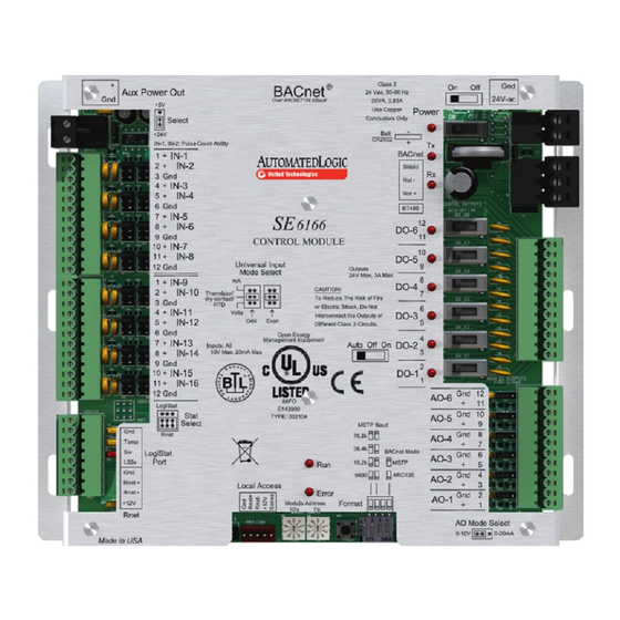
Page 27: Appendix - Se6166 Coverplate
Port LS5v 19.2k MSTP 9600 ARC156 AO-2 Rnet + Local Access Rnet - Error AO-1 Format +12V Module Address 10's Rnet AO Mode Select 0-10V 0-20mA Made in US A SE6166 Controller • Rev. 4/13/2011 © 2011 Automated Logic Corporation...
Need help?
Do you have a question about the SE6166 and is the answer not in the manual?
Questions and answers