Table of Contents
Advertisement
Technical Instructions
U55 1
Mounting 4
LEDs 11
Automated Logic Corporation • 1150 Roberts Blvd. • Kennesaw, GA 30144 • 770/429-3000 • 770/429-3001 Fax •
www.automatedlogic.com • Copyright 2002 Automated Logic Corporation. All rights reserved. Automated Logic, the
Automated Logic logo, SuperVision, Eikon, WebCTRL, Alert, and InterOp are registered trademarks of Automated Logic
®
Corporation. BACnet
is a registered trademark of ASHRAE. All other brand and product names are trademarked by
their respective companies.
Advertisement
Table of Contents

Related Manuals for Automated Logic U551


Summary of Contents for Automated Logic U551
-
Page 1: Table Of Contents
LEDs 11 Production Date 11 Automated Logic Corporation • 1150 Roberts Blvd. • Kennesaw, GA 30144 • 770/429-3000 • 770/429-3001 Fax • www.automatedlogic.com • Copyright 2002 Automated Logic Corporation. All rights reserved. Automated Logic, the Automated Logic logo, SuperVision, Eikon, WebCTRL, Alert, and InterOp are registered trademarks of Automated Logic ®... -
Page 2: U55
ALC • five digital outputs recommends that all time delay functions and • two LogiStat inputs trend intervals in U551 FBs be set to at least one minute. • three general purpose inputs • one analog output... -
Page 3: Job Start-Up
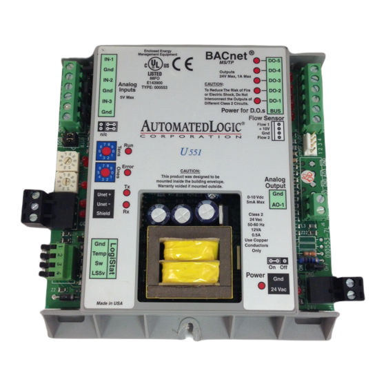
Temp On Off LS5v 24 Vac 0.2" 0.5 cm Figure 1. U551 Layout and Dimensions • UNI/16 with the DRV_UNI16 module Job Start-Up driver, or UNI/32 with the DRV_UNI32 WebCTRL and SuperVision require different module driver module drivers and Eikon software. The appropriate module drivers, Eikon for •... -
Page 4: Start-Up Checklist
Zone GFB option in Eikon for information on daisy-chain, star, and hybrid WebCTRL or Eikon. Refer to “Writing GFBs wiring configurations. for the U551” on page 9 for more information. There is a special wire available that contains 2. Use the appropriate module driver. (See a pair of 14AWG wires for power and a pair of “Job Start-Up”... -
Page 5: Communications Wiring
5. Make sure that 24VAC is present at the module and is automatically detected by the module’s power input terminals. U551. You can set or change the Unet baud 6. Set the module’s address. Refer to rate to 9600 bps or 38.4 kbps on the UNI. The “Addressing”... -
Page 6: Communicating Through The Logistat Port
To communicate through the LogiStat port, NOTE When the LogiStat Adaptor cable the U551 must: is inserted into the LogiPort, the U551 can no longer read the LogiStat inputs. The • be connected to a UNI on an ARC156 U551 continues to use the last valid... -
Page 7: Input Wiring
24AWG shielded and 6. Disconnect the LogiStat Adaptor cable 15 meters grounded to from the LogiStat’s LogiPort when module’s “-” or Gnd finished to allow the U551 to read inputs terminal from the LogiStat. LogiStat 100 feet 22AWG unshielded Sensors... -
Page 8: Digital Output Wiring
Figure 10. Analog Output Wiring Figure 8. Flip Lever Wiring Refer to the section “Writing GFBs for the Be sure the U551’s power is off before wiring U551” on page 9 for more information about any inputs or outputs. Connect the output using a LogiStat sensor. -
Page 9: Writing Gfbs For The U551
W4 jumper as for details. shown in Figure 12 prior to performing test and balance. If you use a flow sensor with the U551, use the Airflow microblock in the U551’s GFB. To connect the sensor, make sure the U551’s IN-1 power is off first. -
Page 10: Point Identifiers
UNI are disrupted. Refer to the number, and minimum and maximum appropriate UNI module driver technical present values for each point on the U551. instruction for instructions on setting up this Select a physical point type from the Point default algorithm. -
Page 11: Leds
The first three characters on LEDs the sticker indicate the type of module. The next two characters show the year and month The U551 modules have diagnostic LEDs to of manufacture. (The month digit is in assist troubleshooting. hexadecimal.) Table 5.
Need help?
Do you have a question about the U551 and is the answer not in the manual?
Questions and answers