
Related Manuals for Exmark ARX440CKC24000


Summary of Contents for Exmark ARX440CKC24000
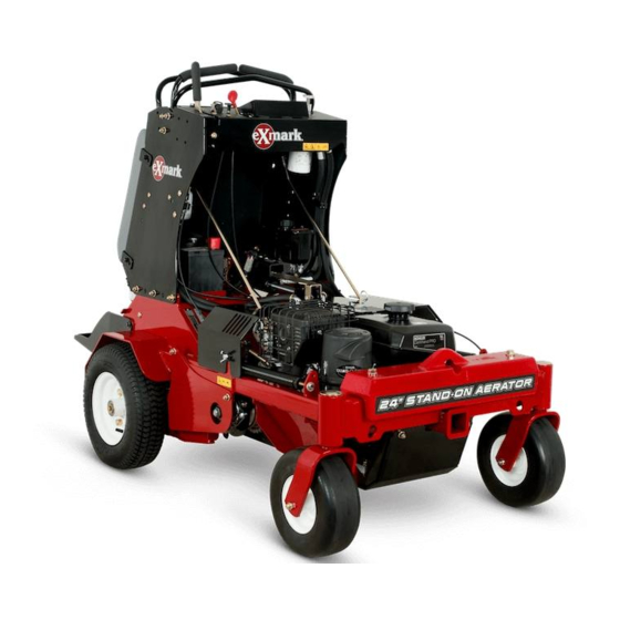
- Page 1 STAND-ON AERATOR 24 INCH MODEL For Serial Nos. 402,082,300 & Higher Part No. 4503-596 Rev. B...
- Page 2 To acquire a spark arrester for your machine, see your Engine Service Dealer. For all models that do not have Exmark engines, please refer to the engine manufacturer's information included with the machine. For models with Exmark engines, refer to this manual for information.
-
Page 3: Introduction
All Exmark parts are thoroughly tested and inspected before leaving the factory, however, attention is required on your part if you are to obtain the fullest measure of satisfaction and performance. -
Page 4: Table Of Contents
Contents Auxiliary Pump Drive Belt Adjustment ...35 Transmission Drive Belt Tension ....35 Drive Wheel Chain Tension Introduction ............3 Adjustment ..........35 Safety ..............5 Tine Drive Chain Adjustment ......35 Safety Alert Symbol ......... 5 Adjusting the Parking Brake......35 Safe Operating Practices ........5 Motion Control Linkage Adjustment ....36 Safety and Instructional Decals ......10 Motion Control Tracking Adjustment .....36... -
Page 5: Safety
DANGER: Indicates an imminently hazardous safely perform the job. Only use accessories and situation which, if not avoided, Will result in death or attachments approved by Exmark. serious injury. • Wear appropriate clothing including safety glasses, WARNING: Indicates a potentially hazardous... - Page 6 Safety DANGER DANGER In certain conditions gasoline is extremely In certain conditions during fueling, static flammable and vapors are explosive. electricity can be released causing a spark which can ignite gasoline vapors. A fire or A fire or explosion from gasoline can burn explosion from gasoline can burn you and you, others, and cause property damage.
- Page 7 Safety Operation – Before refueling. WARNING WARNING Operating engine parts, especially the muffler, Hands, feet, hair, clothing, or accessories can become entangled in rotating parts. Contact become extremely hot. Severe burns can occur with the rotating parts can cause traumatic on contact and debris, such as leaves, grass, brush, etc.
- Page 8 Safety • Identify hazards at the base of the slope. Do • Use extra care while operating with accessories not operate the machine near drop offs, ditches, or attachments. These can change the stability of embankments, water or other hazards. The the machine and cause a loss of control.
- Page 9 Failure to use original Exmark parts could cause serious injury or • Keep sparks, flames, or cigarettes away death. Making unauthorized changes to the from battery.
-
Page 10: Safety And Instructional Decals
Exmark equipment dealer or labels. distributor or from Exmark Mfg. Co. Inc. • Replace all worn, damaged, or missing safety • Safety signs may be affixed by peeling off the signs. - Page 11 Safety decal135-3183 135-3183 1. Bypass lever position for 3. Bypass lever position for pushing the machine. operating the machine. 2. Read the instructions before servicing or decal121-6163 performing maintenance. 121–6163 1. Press to lower the tines. 2. Release to raise the tines.
- Page 12 Safety 135-2013 STOP decal135-2013-1 135-2013 1. Operator weight adjustment 5. Throttle—slow 9. Parking brake—engage 2. Increase 6. Engine—on 10. Parking brake—release 3. Decrease 7. Engine—start 4. Throttle—fast 8. Engine—off decal135-2014b 135-2014 1. Fast 6. Wheels and tines rotate when 11. Thrown object hazard—pick up moving backward debris before operating the machine.
- Page 13 Safety decal135-3685 135-3685 1. Read and understand the operator’s manual before 6. Grease belt idler pivot every 100 hours servicing this machine. 2. Clean and oil chains and check chain tension (2x) every 8 7. Check tire pressure - 23 psi (2x) every 50 hours hours 3.
-
Page 14: Specifications
• Engine Specifications: See your Engine Owner’s of the levers relative to each other. Manual • Tine Ground Engagement: Engages the tines • Engine Oil Type: Exmark 4–Cycle Premium with the ground. Engine Oil • Parking Brake Lever: Engages the parking brake. -
Page 15: Dimensions
Specifications Tires and Wheels Torque Requirements Drive Bolt Location Torque Front Caster Engine Mounting Bolts 27-33 ft-lb (37-45 N-m) Pneumatic Semi-Pneumatic (Air-Filled) Wheel Lug Nuts 85-105 ft-lb (115-142 N-m) Quantity Wheel Hub Bolt 27-33 ft-lb (37-45 N-m) Tread Turf Saver Smooth Transmission Output 211-260 ft-lb... -
Page 16: Product Overview
Operation Product Overview Operation Note: Determine the left and right sides of the machine from the normal operating position. Controls Motion Control Levers The motion control levers, located on each side of the top console, control the forward and reverse motion of the machine. - Page 17 Operation Do Not run a warm engine with choke in the “ON” Pull lever rearward to engage the brake. position. Push the lever forward to disengage the brake. When parking on a steep slope, the wheels must be chocked or blocked in addition to the brake being engaged.
- Page 18 Operation There are two ways to activate the display. Tap the multi-function switch either up or down to display the tine engagement meter. Step on the tine ground engagement foot switch. A higher number on the status bar increases the length of the aeration plug and a lower number decreases it.
- Page 19 Operation during transport to and from the jobsite, and when parked inside a building. Rotate the handle counterclockwise to open; rotate clockwise to 90° to close. Drive Wheel Release Valves WARNING Hands may become entangled in the rotating drive components below the engine deck, which could result in serious injury or death.
-
Page 20: Pre-Start
Operation Operating Instructions This switch can be locked out (disabled) with the multi-function switch. Open the Fuel Shut-Off Valve • Tap and hold the bottom of the switch to override and lock out (disable) the foot switch. The LED Rotate the lever counterclockwise to open. illuminates in the hour meter/tine engagement display. - Page 21 Operation Lower the tines by pressing on the tine ground adjustment control counterclockwise to lower engagement foot switch. The LED indicator the machine until the tires touch the ground. should illuminate under the tine down position • If the tines are not touching the ground, on the hour meter.
- Page 22 Operation Remove the key to prevent children or other unauthorized persons from starting the engine. Close the fuel shut-off valve when the machine will not be in use for a few days, when transporting, or when the unit is parked inside a building.
-
Page 23: Transporting
Operation g016673 Figure 13 g231460 Figure 14 1. Two nuts 2. Front reference/speed To turn left or right, release pressure on the control bar motion control lever toward the desired turn direction. Move the bar forward to obtain the fastest speed. To make zero turns, lift your foot off of the tine ground engagement foot switch to raise the tines. - Page 24 Operation wide enough to extend beyond the rear tires is recommended instead of individual ramps for each side of the machine. With the platform up, a full width ramp provides a surface to walk on behind the machine. If it is not possible to use one full width ramp, use enough individual ramps to simulate a full width continuous ramp.
-
Page 25: Maintenance
Maintenance Maintenance Note: Determine the left and right sides of the machine from the normal operating position. WARNING WARNING While maintenance or adjustments are being The engine can become very hot. Touching a hot made, someone could start the engine. engine can cause severe burns. -
Page 26: Periodic Maintenance
“FULL” battery performance and life, recharge batteries in mark on the dipstick. Exmark 4-Cycle Premium storage when the open circuit voltage drops to 12.4 Engine Oil is recommended; refer to the Engine volts. - Page 27 Maintenance short lengths to reduce voltage drop between Voltage Percent Maximum Charging systems. Make sure the cables are color coded or Reading Charge Charger Interval labeled for the correct polarity. Settings 12.6 or 100% 16 volts/7 CAUTION Charging greater amps Required Connecting the jumper cables incorrectly 12.4 –...
-
Page 28: Check Tines
Maintenance CAUTION Raising the unit for service or maintenance relying solely on mechanical or hydraulic jacks could be dangerous. The mechanical or hydraulic jacks may not be enough support or may malfunction allowing the unit to fall, which could cause injury. Do Not rely solely on mechanical or hydraulic jacks for support. -
Page 29: Check The Safety Interlock
Maintenance Check the Safety Interlock Important: It is essential that the operator safety mechanisms be connected and in proper operating condition prior to use. Note: If machine does not pass any of these tests, Do Not operate. Contact an Authorized Service Dealer. Check the Normal Engine Starting Circuit System Parking Brake... -
Page 30: Check For Loose Hardware
Before the new filter is installed, Service Interval: Before each use or daily apply a thin coating of Exmark 4–Cycle Premium Stop engine, wait for all moving parts to stop, and Engine Oil on the surface of the rubber seal. -
Page 31: Check Tire Pressures
Maintenance Check Tire Pressures Shut off the engine, wait for all moving parts to stop, and remove the key. Engage the parking Service Interval: Every 50 hours brake. Stop engine, wait for all moving parts to stop, and Lift the rear of the machine and support using remove key. -
Page 32: Check Spark Plug
Service Interval: After the first 100 hours Important: Before reinstalling new filters, Every 250 hours thereafter apply a thin coat of Exmark Premium Hydro Oil on the surface of the filters rubber seal. Stop engine, wait for all moving parts to stop, and remove key or spark plug wire(s). -
Page 33: Check Transmission Output Shaft Nut Torque Specification
Output Shaft Nut Torque Torque plugs to 180 in-lb (20 N-m). Continue to Specification add Exmark Premium Hydro Oil until it reaches the FULL COLD line on the expansion reservoir. Service Interval: After the first 5 hours Raise the rear of machine up and support with... -
Page 34: Check Spark Arrester (If Equipped)
Maintenance Thread Locking Adhesives Check Spark Arrester (if equipped) Thread locking adhesives such as “Loctite 242” or “Fel-Pro, Pro-Lock Nut Type” are used on the Service Interval: Every 50 hours following fasteners: WARNING Sheave retaining bolt in end of engine crankshaft. Hot exhaust system components may ignite All set screws. -
Page 35: Adjustments
Maintenance Adjustments Check the chains on each side of the idler sprocket, on both sides of the machine, for proper Note: Shut off engine, wait for all moving parts to tension. The chains should be able to move up stop, engage parking brake, and remove key before and down 1/4-1/2 inch (6-12 mm). -
Page 36: Motion Control Linkage Adjustment
Maintenance g233407 g231567 Figure 18 Figure 19 1. Adjustment nut 1. Hex adjustment linkage jam nut Tighten the cable adjustment nut and engage the Allow the control levers to return to neutral. park brake. Turn the LH hex adjustment link until the motion control levers are approximately even with each Check the park brake;... -
Page 37: Return-To-Up Spring Adjustment
Maintenance g233418 Figure 20 1. Adjustment rod g233568 Figure 21 Looking down towards the adjustment rod — 1. 1.38 inch (35 mm) rotate it counterclockwise, in 1/4 turn increments, to increase speed or clockwise to decrease speed. Important: The springs must be replaced it the Drive the machine and check the full forward gap is less than 1.13 inches (29 mm). -
Page 38: Cleaning
Maintenance Cleaning guards, around the fuel tank, around engine and exhaust area. Clean Engine and Exhaust Waste Disposal System Area Service Interval: Before each use or daily Motor Oil Disposal (May be required more Engine oil and hydraulic oil are both pollutants to often in dry or dirty the environment. -
Page 39: Troubleshooting
Troubleshooting Troubleshooting Important: It is essential that all operator safety mechanisms be connected and in proper operating condition prior to use. When a problem occurs, do not overlook the simple causes. For example: starting problems could be caused by an empty fuel tank. The following table lists some of the common causes of trouble. - Page 40 Troubleshooting Problem Possible Cause Corrective Action Engine overheats. 1. Engine load is excessive. 1. Reduce the ground speed or aeration depth. 2. Oil level in the crankcase is low. 2. Add oil to the crankcase. 3. Cooling fins and air passages for the 3.
-
Page 41: Schematics
Schematics Schematics Electrical Schematic B+ START g231578... - Page 42 Schematics Hydraulic Schematic g243786...
- Page 44 Pack) or Fill in Below Engine Model No. and Spec. No. Model No. Engine Serial No. (E/No) Serial No. ©2018 Exmark Mfg. Co., Inc. Part No. 4503-596 Rev. B 2101 Ashland Ave (402) 223-6375 Beatrice, NE 68310 Fax (402) 223-5489...
Need help?
Do you have a question about the ARX440CKC24000 and is the answer not in the manual?
Questions and answers