Advertisement
Quick Links
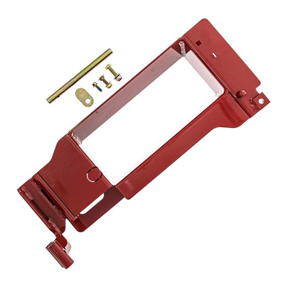
Accessory Adapter Kit
Kit No. 135-5313
Loose Parts
Use the chart below to verify that all parts have been
shipped.
Item Part No.
Description
1
135-5314-01 Wld-Adapter Accessory
2
323-7
Screw-HH 3/8-16 x 1 1/4
3
3230-2
Bolt-Carriage 5/16-18 x 1
4
104-8300
Nut-Nyloc 5/16-18 Flg
© 2019—Exmark Mfg. Co., Inc.
2101 Ashland Ave
Beatrice, NE 68310
Qty
Item Part No.
1
5
1-353054
1
6
104-8301
1
7
116-7024
1
8
117-8304
Figure 1
www.Exmark.com
Form No. 4504-516 Rev A
Installation Instructions
Description
Latch-Catcher, Grass
Nut-Nyloc 3/8-16 Flg
Pin-Mount
Screw-Hex Flange 1/4-20 x 3/4
Original Instructions (EN)
All Rights Reserved *4504-516* A
Printed in the USA
Qty
1
1
1
1
g287257
Advertisement

Related Manuals for Exmark 135-5313


Summary of Contents for Exmark 135-5313
- Page 1 Bolt-Carriage 5/16-18 x 1 104-8300 Nut-Nyloc 5/16-18 Flg 117-8304 Screw-Hex Flange 1/4-20 x 3/4 g287257 Figure 1 © 2019—Exmark Mfg. Co., Inc. www.Exmark.com Original Instructions (EN) All Rights Reserved *4504-516* A 2101 Ashland Ave Printed in the USA Beatrice, NE 68310...
- Page 2 Safety Alert Symbol Installing the Adapter Kit This Safety Alert Symbol (Figure 2) is used both in DANGER this instruction sheet and on the machine to identify important safety messages which must be followed to An uncovered discharge opening will allow avoid accidents objects to be thrown in an operator’s or This symbol means: ATTENTION! BECOME ALERT!
- Page 3 Rotate the latch downward to lock the assembly in this position. Adjust the tension on the latch to hold the assembly up to the deck, yet allow for release by hand. Tension can be adjusted by tightening or loosening the hardware that retains the latch.
Need help?
Do you have a question about the 135-5313 and is the answer not in the manual?
Questions and answers