
Related Manuals for Honeywell Touchpoint 1


Summary of Contents for Honeywell Touchpoint 1
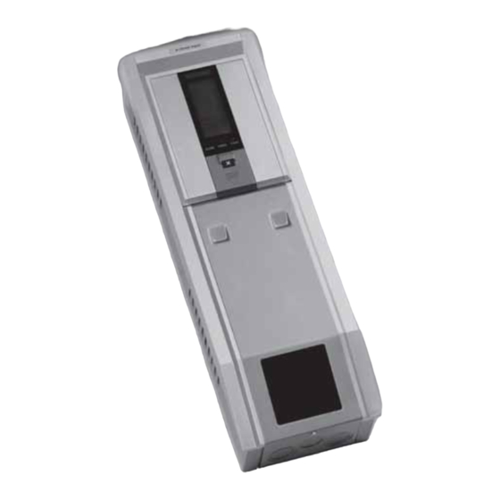
- Page 1 Technical Manual Touchpoint 1 Single Channel Gas Detector Controller TP1MAN Issue 3 Apr 06 (MAN0630)
- Page 2 TP1MAN Issue 3 Apr 06 (MAN0630)
-
Page 3: Safety
Technical Manual. Cautions appear in the sections/sub-sections of the document where they apply. WARNINGS Touchpoint 1 is designed for installation and use in indoor safe area non-explosive atmospheres. Installation must be in accordance with the recognized standards of the appropriate authority in the country concerned. -
Page 4: Information
Information Information Honeywell Analytics can take no responsibility for installation and/or use of its equipment if this is not done in accordance with the appropriate issue and/or amendment of the Technical Manual. The reader of this Technical Manual should ensure that it is appropriate in all details for the exact equipment to be installed and/or operated. -
Page 5: Table Of Contents
Contents Contents Safety Information Introduction Enclosure Display Module Terminal Module General Installation Location Dimensions Mounting Controller Components Power Cabling Wiring Zareba Sensepoint Gas Detector Connections Generic Gas Detector Connections Maximum Cable Lengths Operation Powering Up Information on the Display Status Indications Control Buttons Menus Using Menus... -
Page 6: Display Module
Power Source Default Configuration mV input detector 4-20 mA input detector Maintenance General Maintenance Troubleshooting System Configuration Check Sheet System Review Check Sheet/Record Parts Touchpoint 1 Controllers Spares Specifications General Environmental Inputs Outputs Warranty TP1MAN Issue 3 Apr 06 (MAN0630) -
Page 7: Installation
Installation Installation WARNINGS Touchpoint 1 is designed for installation and use in indoor safe area non-explosive atmospheres. Installation must be in accordance with the recognized standards of the appropriate authority in the country concerned. Before carrying out any work ensure local regulations and site procedures are followed. -
Page 8: Enclosure
Installation • enough space to open the enclosure’s access panels, for cabling, maintenance, adjustments, etc. • enough space for cable or conduit access to the bottom of the enclosure Follow the advice of: • experts having specialist knowledge of gas detection and control systems •... -
Page 9: Mounting
(3.9”) Mounting Touchpoint 1 is supplied with a mounting bracket that fits onto a suitable wall. The controller is then hooked onto the bracket. The previous diagrams show dimensions for Touchpoint 1 and the bracket. Fit the bracket to a flat, firm surface, e.g. wall, suitable for the controller’s size and weight. -
Page 10: Controller Components
Installation Controller Components This procedure describes how to access the components inside the controller. Loosen the single captive screw securing the Terminal Module access panel. The panel is located at the bottom of the enclosure. Push down on the finger grips at the top of the access panel. Slide the panel down to release it. -
Page 11: Power
Caution Always ensure the cover is replaced/refitted after work is complete. Power Touchpoint 1 has an auto sensing power supply capable of operating between 85 and 265 Vac, 50/60 Hz mains supply, and/or 19 to 32 Vdc. Honeywell Analytics recommend that the power to the controller is sourced from a locally fused circuit. -
Page 12: Wiring
Installation To calculate the maximum cable run length from the controller to the detector see page 23. Neutral Live AC Supply Earth Star Ground/Earth Point Gas Detector Signal Wiring Caution An earth point is provided inside the controller. Ensure that all detector screens/armor are grounded at a single earth star point at the controller or detector —... - Page 13 Installation Always use suitable wiring techniques and crimps when terminating cable cores, especially if running two cores to a single terminal. Signal and DC power connections are made via a 16-wire terminal block. Mains power is connected via a separate 3-wire terminal block. The diagram shows the 16-wire terminal block layout with terminal identifiers.
- Page 14 Installation Input/ Id. Name Function Specification Output N/O Contact Common Fault Relay Outputs 240 Vac, 3 A max. N/C Contact DC supply/ DC Power battery back- Inputs 18 to 32 Vdc DC– N/O Contact Common Alarm Relay 2 Outputs 240 Vac, 3 A max. N/C Contact * Signal current Repeated 4-...
-
Page 15: Zareba Sensepoint Gas Detector Connections
Earth/Ground Zareba Sensepoint Gas Detector Connections Touchpoint 1 is specifically designed for use with the Sensepoint range of gas detectors. The subsequent diagrams show connection details for these units. For further information about Sensepoint detectors refer to their individual technical manuals/ data sheets. - Page 16 Installation TP1MAN Issue 3 Apr 06 (MAN0630)
- Page 17 Installation TP1MAN Issue 3 Apr 06 (MAN0630)
- Page 18 Installation TP1MAN Issue 3 Apr 06 (MAN0630)
- Page 19 Installation TP1MAN Issue 3 Apr 06 (MAN0630)
-
Page 20: Generic Gas Detector Connections
Installation Generic Gas Detector Connections The following diagrams show generic installation connections for other gas detectors. 3-Wire mV Detector Controller Detector Signal Signal 3-Wire 4-20 mA Detector Controller Detector Signal Signal TP1MAN Issue 3 Apr 06 (MAN0630) -
Page 21: Maximum Cable Lengths
Installation 2-Wire 4-20 mA Detector Controller Detector Signal Signal 100 Ohms Maximum Cable Lengths To calculate the maximum cable run length from power source to the detector refer to the following example diagram and formula. = (V — V ) / I loop controller detector min... - Page 22 Installation Detector supply Cable run Controller Signal s ensor TP1MAN Issue 3 Apr 06 (MAN0630)
-
Page 23: Operation
Once powered, Touchpoint 1 displays gas concentration, alarm, fault and status information on its view screen. Touchpoint 1 is controlled and configured interactively via a menu system and a set of control buttons. This chapter provides operational information about the following: •... -
Page 24: Information On The Display
Operation Information on the Display The controller features a user interface that, during normal operation, displays gas reading information, and also system fault and information messages. It displays status and configuration information about the system via a menu options accessed and controlled via four buttons (3 are hidden) below the display, see page 31 and page 32. - Page 25 Operation Status 4-20 mA Output Operational Examples Audible State Display Relays (for 200ppm range) Alarm Alarm Relay 1 de-energized Alarm Relay 2 de-energized Fault relay energized Normal (default) operation Alarm set point indicators (bars) flash ALARM POWER FAULT Alarm Relay 1 energized Alarm 1 Alarm Relay 2 de-energized 8.16 mA...
- Page 26 Operation Status 4-20 mA Output Operational Examples Audible State Display Relays (for 200ppm range) Alarm Alarm Relay 1 energized Alarm 2 Alarm Relay 2 energized 15.84 mA Fault relay energized ALARM POWER FAULT Greater than Alarm Relay 1 energized full scale Alarm Relay 2 energized 22 mA alarm...
- Page 27 Operation Status 4-20 mA Output Operational Examples Audible State Display Relays (for 200ppm range) Alarm Alarm Relay 1 de-energized Deadband Alarm Relay 2 de-energized (negative drift 3.2 - 4 mA Fault relay de-energized (default <5%) energized in normal operation) ALARM POWER FAULT Fault...
- Page 28 Operation Status 4-20 mA Output Operational Examples Audible State Display Relays (for 200ppm range) Alarm Fault Alarm Relay 1 de-energized (open/short Alarm Relay 2 de-energized 0 mA circuit) Fault relay de-energized Alarm Relay 1 de-energized Inhibit Alarm Relay 2 de-energized 1.5 - 2.5 mA Fault relay energized LED on...
-
Page 29: Control Buttons
Operation Control Buttons The control buttons are located beneath an access panel underneath the display screen. They are used to cancel alarms and access/navigate the menu system. To access the buttons carry out the following procedure: Access the controller interior. See page 12. -
Page 30: Menus
Operation Menus Touchpoint 1 has 6 menus for configuring/controlling the unit. They are represented on the display by the icons shown in the following table lists them and explains what they are for. Menu Description Function More information Gas units/range... -
Page 31: Cancelling Operations/Choices
Operation Cancelling Operations/Choices To cancel operations/choices: Press the — Cancel — button. This returns to the previous menu level, setting, etc. Pressing Cancel again returns to normal operation. Note The system automatically returns to normal operation if no buttons are pressed for more than 30 minutes. -
Page 32: Commissioning
Caution Calibration of the gas detector and the controller is mandatory during commissioning to ensure their proper functioning. This chapter describes how to put the two versions of Touchpoint 1 into service with the following different types of gas detectors: •... - Page 33 Commissioning Apply power to the controller and switch it on. See page 25. To skip the warm up sequence press the Cancel button for 3 seconds. Check for a minimum voltage of 2.9 Vdc at the detector. If incorrect check for constant current supply of 200 mA +/-2 mA.
-
Page 34: 2-Wire 4-20 Ma Sink
Check for a minimum voltage of 16 Vdc at the gas detector. For detectors other than Sensepoint Toxic/Oxygen refer to their operating instructions. Check that the Touchpoint 1 display shows the correct gas units and range for the detector in use. -
Page 35: 3-Wire 4-20 Ma Source
Commissioning 3-wire 4-20 mA Source This covers connection to gas detectors such as Sensepoint Plus and Sensepoint Pro. Set up the gas detector. Refer to the detector’s user manual for details describing how to set up the detector. Check that all power and electrical connections to the controller, and electrical connections to the gas detector are correct. -
Page 36: User Settings
38 • set zero and span, see page 40 • browse Touchpoint 1’s event record, see page 41 • set alarm levels and relay actions, see page 42 • set the real-time clock, see page 44 •... - Page 37 User Settings TP1MAN Issue 3 Apr 06 (MAN0630)
-
Page 38: Zero And Span
Apply calibration (span) gas to the detector at a flow rate of 0.3 l/min. Note Honeywell Analytics recommend the use of half full-scale gas for calibration purposes (contact a distributor for the supply of calibration gas). The gas reading on the controller display shows the measured reading from the detector When the gas reading is stable adjust the reading to the actual concentration of the calibration gas being applied to the detector. -
Page 39: Event History
User Settings Press OK. The display then shows a 10 second countdown. When the countdown is complete the display shows GOOD if the span has succeeded. If the span fails the display shows FAIL and returns to the beginning of the span menu. Press OK. -
Page 40: Alarm Levels And Relay Action
User Settings To view the other 9 records repeat the procedure. Note The time and date for each record is shown at the bottom of the display in a sequence of three parts. Each part is displayed for 2 seconds. For example if the time for the record is 18 minutes past 12 o'clock on July 27th, 2004 then the display shows: •... - Page 41 User Settings Press OK to accept the change. The display changes to the A1 relay action menu. The display shows either r 1-d (for relay 1 de- energized), or r 1-E (for relay 1 energized). Use Up/Down to change the relay action. Press OK to accept the change.
-
Page 42: Time And Date
User Settings Alarm 2 settings are changed in the same way as for Alarm 1. A2 alarm levels can be set between the A1 alarm level and the full scale range. The default setting is 50% of the full scale range. Press OK to accept the changes. -
Page 43: Power Source
Press Cancel. Returns controller to normal operation. Power Source This menu programs Touchpoint 1 for the type of available power source(s). The controller can be set to any of three different power supply modes. Access the menu system and select the menu option. -
Page 44: Mv Input Detector
User Settings mV input detector Function Default Configuration Display range and units 0-100% LEL mV Signal <2.9 mV Fault (open circuit) 2.9 - 3.5 mV Normal operation >3.5 mV Overrange Alarm Relay 1* Alarm level 1 — 20% LEL Latching, normally de-energized, energizes on alarm (Single Pole Change Over 240 Vac 3A max) Alarm Relay 2* Alarm level 2 —... -
Page 45: Maintenance
Maintenance Maintenance WARNINGS Touchpoint 1 is designed for installation and use in indoor safe area non-explosive atmospheres. Installation must be in accordance with the recognized standards of the appropriate authority in the country concerned. Before carrying out any work ensure local regulations and site procedures are followed. -
Page 46: Troubleshooting
Maintenance Troubleshooting The following table details self diagnostics/problem solving for Touchpoint 1. Configuration Fault Symptom Action Condition Power Supply Faults — subject to selected settings DC1 normal: All LEDs & display off/not AC supply failed AC voltage ≥ Power LED (green) ON working. - Page 47 Maintenance Troubleshooting The following table details self diagnostics/problem solving for Touchpoint 1. Configuration Fault Symptom Action Condition Power Supply Faults — subject to selected settings DC1 normal: All LEDs & display off/not AC supply failed AC voltage ≥ Power LED (green) ON working.
-
Page 48: System Configuration Check Sheet
Maintenance System Configuration Check Sheet Controller location Installed by Date Configured by Date Calibrated by Date Contact tel no Power supply ..AC volts ..DC volts Type SensePoint detector type Other detector Channel type mV input mA input Toxic Oxygen Flam. -
Page 49: Parts
Maintenance System Review Check Sheet/Record Company Name Application Details Contact Name Address Mobile Email (Brief application and system overview including ancillary devices) Customer reported problems/specific requests Checklist Control System Comments Is control system mounted in a suitable place? Daily viewing, access for maintenance? Is protection suitable for location? Indoor/outdoor, enclosure IP /NEMA rating? Are there any visual signs of damage? -
Page 50: Specifications
Specifications Specifications General Wall mounted single channel control panel for the local annunciation of gas hazards as detected by the Zareba range of Sensepoint gas detectors. Suitable for small scale, indoor installations requiring a self contained gas detection and control system User interface Single Test/Accept/Reset push-button for normal operational use. -
Page 51: Inputs
Specifications Inputs 85-265Vac, 50/60Hz auto-sensing, 18-32 Vdc, maximum power 30 Wac and/ Supply or 15Wdc 2 wire, 4-20 mA, 3 wire, 4-20 mA, Detector Type 3 wire mV bridge loop powered source output Sensepoint Toxic Sensepoint Plus Example Sensepoint Flammable and Oxygen and Sensepoint Pro mV Bridge Input Module... -
Page 52: Warranty
All products are designed and manufactured to the latest internationally recognized standards by Honeywell Analytics under a Quality Management system that is certified to ISO 9001. As such Honeywell Analytics warrants its products against defective parts and workmanship and will... - Page 53 CH-8610 Uster Switzerland Tel: +41 (0)44 943 4300 Fax: +41 (0)44 943 4398 gasdetection@honeywell.com Americas Honeywell Analytics Distribution, Inc. 400 Sawgrass Corporate Pkwy Suite 230 Sunrise, FL 33325 Tel: +1 954 514 2700 Toll free: +1 800 538 0363 Fax: +1 954 514 2784 detectgas@honeywell.com...
Need help?
Do you have a question about the Touchpoint 1 and is the answer not in the manual?
Questions and answers