
Related Manuals for Bender RC48N-70-10 A


Summary of Contents for Bender RC48N-70-10 A
- Page 1 Operating Manual RC48N-70-10 A RC48N-70-50 A Ground-fault and neutral-grounding monitoring system Power in electrical safety TGH1397en/11.2006...
- Page 2 Dipl.-Ing. W. Bender GmbH & Co.KG Londorfer Str. 65 • 35305 Grünberg • Germany Postfach 1161 • 35301 Grünberg • Germany Tel.: +49 (0)6401-807-0 Fax: +49 (0)6401-807-259 © Dipl.-Ing. W. Bender GmbH & Co.KG E-mail: info@bender-de.com Web server: http://www.bender-de.com All rights reserved.
-
Page 3: Table Of Contents
Table of Contents 1. How to get the most out of this manual ............. 5 How to use this manual ......................5 Explanations of symbols and notes ................... 5 2. Safety instructions ....................7 Intended use ..........................7 Qualified personnel ......................... 7 General safety instruction ..................... - Page 4 Table of Contents TGH1397en/11.2006...
-
Page 5: How To Get The Most Out Of This Manual
Please read this operating manual and the enclosed sheet entitled "Important safety instruc- tions for BENDER products" before using the equipment. This document must be kept in an easily accessible location near to the equipment. - Page 6 How to get the most out of this manual This symbol indicates important information about the correct use of the equip- ment purchased. Failure to observe the associated instructions can result in equipment malfunc- tioning or cause problems in the environment in which it is being used. This symbol indicates tips for using the equipment and particularly useful infor- mation.
-
Page 7: Safety Instructions
BENDER equipment is designed and built in accordance with the state of the art and accept- ed rules in respect of technical safety. However, the use of such devices may introduce risks to the life and limb of the user or third parties and/or result in damage to BENDER equip- ment or other property. -
Page 8: Warranty And Liability
ER within the guarantee period. In order for claims made under the terms of the guarantee to be accepted, BENDER must acknowledge that the product is faulty and that the fault con- cerned cannot be attributed to the incorrect handling or modification of equipment, non- compliant use or abnormal operating conditions. -
Page 9: System Description
3. System description 3.1 Features 3.1.1 Areas of application Installations featuring high-resistance neutral-earthing are used whenever power supply fail- ure would incur significant costs due to production downtimes (e.g. the automotive industry, chemicals industry). With this type of installation, an insulation fault between a phase and the earth will not result in failure of the power supply. -
Page 10: Mechanical Design
System description 3.1.3 Mechanical design The RC48N-70... ground-fault and neutral-grounding monitoring system consists of a steel plate housing containing the following built-in components. Assembly plan RC48N-70-10A: ALARM RC48N-935 CD1000 W0-S15 W0-S15 Mounting plate: Used for mounting all the components directly or by means of DIN- rails. -
Page 11: Installation And Connection
4. Installation and connection Before mounting the device and working on the device connections, make sure that the voltage has been disconnected. Failure to comply with this requirement will expose personnel to the risk of electric shock. Furthermore, the electrical installation may sustain damage and the device be Danger ! destroyed beyond repair. -
Page 12: Connection
Installation and connection 4.2 Connection 4.2.1 Connection diagram RC48N-70-10A TGH1397en/11.2006... - Page 13 Installation and connection Key for connection diagram RC48N-70-10A Devices RC48N-935 ground-fault and neutral-grounding monitor Coupling device CD1000 enables the voltage to be measured between the trans- former neutral and earth up to a maximum of 1000 V AC. Measuring current transformer W0-S15 to detect the current flowing through the NER.
-
Page 14: Connection Diagram Rc48N-70-50A
Installation and connection 4.2.2 Connection diagram RC48N-70-50A TGH1397en/11.2006... - Page 15 Installation and connection Key for connection diagram RC48N-70-50A Devices RC48N-935 ground-fault and neutral-grounding monitor Coupling device CD1000 enables the voltage to be measured between the trans- former neutral and earth up to a maximum of 1000 V AC. -T2, -T3 Measuring current transformer W0-S15 to detect the current flowing through the NER.
- Page 16 Installation and connection TGH1397en/11.2006...
-
Page 17: Operation And Configuration
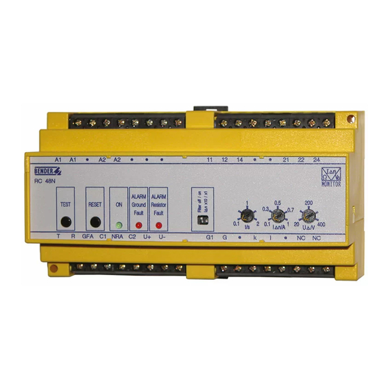
5. Operation and configuration 5.1 Operating elements RC48N-70-10A • • • • • • ALARM RC48N MONITOR ALARM ALARM Ground Resistor TEST RESET Fault Fault t / s GFA C1 NRA C2 • • NC NC Master switch S1: Monitoring ON/OFF Press the TEST key to initiate the following sequence: A test residual current is simulated and once the response time has elapsed, an alarm is recognised;... -
Page 18: Operating Elements Rc48N-70-50A
Operation and configuration 5.2 Operating elements RC48N-70-50A • • • • • • ALARM RC48N x100 MONITOR ALARM ALARM TEST RESET Ground Resistor Fault Fault t / s GFA C1 NRA C2 • • NC NC Master switch S1: Monitoring ON/OFF Press the TEST key to initiate the following sequence: A test residual current is simulated and once the response time has elapsed, an alarm is recognised;... -
Page 19: Setting The Alarm Relay Operating Mode
5.3 Setting the alarm relay operating mode You can set the operating mode for the alarm relay via a bridge between the NC-NC contacts on the RC48N-935: 14 21 22 24 RC48N-935 GFA NRA C1 C2 NC NC Bridge open N/O operation Bridge closed N/C operation (factory setting) - Page 20 Operation and configuration TGH1397en/11.2006...
-
Page 21: Data
Data 6. Data 6.1 Technical data Insulation coordination acc. to IEC 60664-1 Rated insulation voltage............................AC 250 V Rated impulse withstand voltage/contamination level..................2.5 kV/3 Voltage ranges Supply voltage U ......................AC/DC 60 ... 264 V, 50 ... 60 Hz, Fuse............................recommended: 6 A slow fuse Power consumption ........................approx. -
Page 22: Applied Standards
Data General data Operating temperature ....................- 40 °C ...+ 60 °C (233 K ... 333 K) Storage temperature......................- 55 °C ... + 80 °C (218 ... 353 K) Climatic class according to IEC 60721 .......................... 3K5 Operating mode ..........................continuous operation Mounting.............................. - Page 23 INDEX Symbols Intended use 7 “ALARM Ground Fault” LED “ALARM Resistor Fault” LED Measuring current transformer Alarm lamp H3 17 NER 9 Alarm relay 13 Neutral earthing resistor (NER) Alarm relay operating mode 19 Areas of application 9 personnel 7 Bridge 19 RESET key 17 Response value 17...
- Page 24 INDEX TGH1397en/11.2006...
- Page 26 Dipl.-Ing. W. Bender GmbH & Co.KG Londorfer Str. 65 • 35305 Grünberg • Germany Postfach 1161 • 35301 Grünberg • Germany Tel.: +49 (0)6401-807-0 Fax: +49 (0)6401-807-259 E-Mail: info@bender-de.com Web server: http://www.bender-de.com...
Need help?
Do you have a question about the RC48N-70-10 A and is the answer not in the manual?
Questions and answers