
Related Manuals for Bender LINETRAXX RCMA423


Summary of Contents for Bender LINETRAXX RCMA423
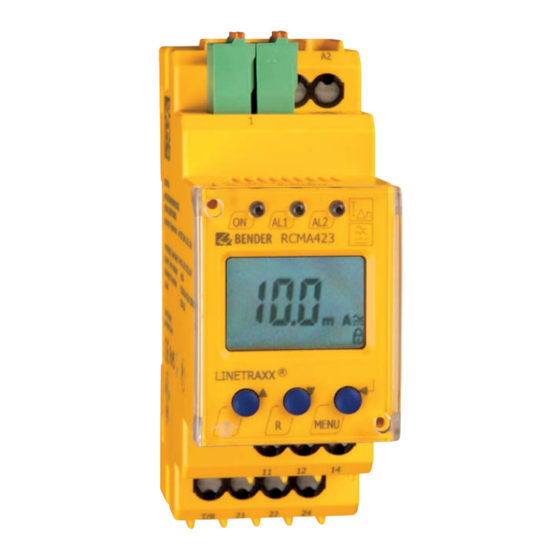
- Page 1 Manual EN LINETRAXX® RCMA423 Residual current monitor for monitoring AC- and (pulsed) DC-currents I = 30 mA…3 A Δ in TN- and TT systems RCMA423_D00063_04_M_XXEN/12.2023...
- Page 2 RCMA423_D00063_04_M_XXEN/12.2023...
-
Page 3: Table Of Contents
Indication of important instructions and information...............5 Signs and symbols............................5 Service and Support............................5 Training courses and seminars........................6 Delivery conditions............................6 Inspection, transport and storage......................6 Warranty and liability.............................6 Disposal of Bender devices..........................7 1.10 Safety..................................7 Function.......................8 Intended use..............................8 Device features..............................8 Function................................8 2.3.1... - Page 4 Table of contents Operation and setting..................13 Display elements in use..........................13 Function of the operating elements......................14 Menu structure...............................14 Display in standard mode..........................16 Display in menu mode..........................16 Parameter settings................... 18 Response value setting for overcurrent....................18 Fault memory..............................19 Alarm relays..............................19 Alarm categories............................20 Set the time delays............................21 Changeover: overcurrent/undercurrent/window mode..............
-
Page 5: General Information
Protect from dust Temperature range Recycling RoHS directives Service and Support Information and contact details about customer service, repair service or field service for Bender devices are available on the following website: Fast assistance | Bender GmbH & Co. KG. RCMA423_D00063_04_M_XXEN/12.2023... -
Page 6: Training Courses And Seminars
Regular face-to-face or online seminars for customers and other interested parties: www.bender.de > know-how > seminars. Delivery conditions The conditions of sale and delivery set out by Bender GmbH & Co. KG apply. These can be obtained in printed or electronic format. The following applies to software products: ‘Software clause in respect of the licensing of standard software as part of deliveries,... -
Page 7: Disposal Of Bender Devices
LINETRAXX® RCMA423 Disposal of Bender devices Abide by the national regulations and laws governing the disposal of this device. For more information on the disposal of Bender devices, refer to www.bender.de > service & support. 1.10 Safety If the device is used outside the Federal Republic of Germany, the applicable local standards and regulations must be complied with. -
Page 8: Function
Function Function Intended use The AC/DC sensitive residual current monitor RCMA423 is designed for use in earthed systems (TN and TT systems) where DC and AC fault currents may occur. These are in particular loads containing six-pulse rectifiers or one way rectifiers with smoothing, such as converters, battery chargers, construction site equipment with frequency-controlled drives. -
Page 9: Connection Monitoring
2.3.5 Functional faults If an internal functional fault occurs, all three LEDs flash. An error code will appear on the display (E01…E32). In such a case please contact the Bender Service. 2.3.6 Set the number of reload cycles If faults occur only temporarily, but recurrently, in the system being monitored, with the fault memory M deactivated, the alarm relays would switch synchronously to the error status. -
Page 10: Residual Current Monitoring In Window Discriminator Mode
Function If the residual current increases above or falls below the response value the response time t expires. After the expiry of the response time an alarm is signalled. A set response delay t (0…10 s) adds up to the device- on1/2 related operating time t and delays alarm signalling (total delay time t... -
Page 11: Installation, Connection And Commissioning
LINETRAXX® RCMA423 Installation, connection and commissioning Only skilled persons are permitted to carry out the work necessary to install, put into service and run a device or system. DANGER Risk of fatal injury due to electric shock! Touching live parts of the system carries the risk of: •... -
Page 12: Commissioning
Installation, connection and commissioning Wiring diagram –12V +12V CTX... CTUB101- S1(k) S2(l) CTBC... +12V –12V T 11 12 21 22 Terminal Connections A1, A2 Connection for supply voltage Us Socket for the connecting cable CTX… to the measuring current transformer Connection for combined test and reset button 11, 12, 14 Alarm relay K1... -
Page 13: Operation And Setting
LINETRAXX® RCMA423 Operation and setting Display elements in use A detailed description of the meaning of the display elements in use is given in the table below. RI. n12 > < onoffHysM Display-Elemente Element Function Reload function with memory = off (L = I.) Response value I as mA (Alarm 2, main alarm) Response valueI... -
Page 14: Function Of The Operating Elements
Operation and setting Function of the operating elements Operating elementes Element Function LED ON lighting continuously: Power On ON, green Flashing LED ON: System fault or connection monitoring fault LED AL 1 lights: Response value 1 reached (I AL1, yellow LED AL 2 lights: Response value 2 reached (I AL2, yellow Test button (>... - Page 15 LINETRAXX® RCMA423 Menu Sub menu Menu item Activation Adjustable parameter Fault memory Operating mode K1 (n.c.) Operating mode K2 (n.c.) Reload function (memory = off ) 1 Err Device error at K1 PrewarningI at K1 r1 I1 r1 (K1: assignment (output alarm category) Main alarm I...
-
Page 16: Display In Standard Mode
Operation and setting Display in standard mode By default, the currently measured residual current is displayed. The current response values I1 (prewarning) and I2 (alarm) can be displayed using the Up and Down key. Press the Enter key to return to the measured value. - Page 17 LINETRAXX® RCMA423 Menu item Adjustable parameter Configuration of the fault memory and the alarm relays • Activate/deactivate the fault memory or assign continuous mode (on/off/con) • Select N/O operation (n.o.) or N/C operation (n.c.) individually for each K1/K2 • Specify the number of the reload cycles •...
-
Page 18: Parameter Settings
Parameter settings Parameter settings An example is given here on how to change the alarm response value I1 (I ). It is presumed that the option Δn1 overcurrent (HI) has been selected in the SEt/I 12 menu (factory setting). Proceed as follows: Press the MENU/Enter key for more than 1.5 seconds. -
Page 19: Fault Memory
LINETRAXX® RCMA423 Setting the hysteresis of the response values I Δn1 Δn2 > Fault memory Setting the fault memory to con mode Alarm relays Setting the alarm relay K1 to N/O operation (n.o.) RCMA423_D00063_04_M_XXEN/12.2023... -
Page 20: Alarm Categories
Parameter settings Setting the number of reload cycles > 1,5 s Alarm categories Overcurrent, undercurrent and device-related errors of the residual current monitor can be assigned to the alarm relays K1 (r1, 1) and K2 (r2, 2). By default, the alarm relays K1 and K2 signal prewarning and alarm in case of overcurrent and device-related errors. -
Page 21: Set The Time Delays
LINETRAXX® RCMA423 Alarm relay K1: Activating the category response value I2 > 1,5 s Alarm relay K1: Deactivating the category ‘Alarm by device test’ > 1,5 s CAUTION When an alarm relay (K1/K2) has been deactivated in the menu, an alarm will not be signalled by the respective changeover contact! An alarm will only be indicated by the respective alarm LED (AL1/AL2)! Set the time delays The following delays can be set... -
Page 22: Changeover: Overcurrent/Undercurrent/Window Mode
Parameter settings Setting the response delay t > 1,5 s t on t on t on t on Setting the starting delay t > 1,5 s Changeover: overcurrent/undercurrent/window mode The operating mode can be changed in the SEt/I 12 menu using the parameters HI, Lo and In. By default, overcurrent operation (HI) is set. - Page 23 LINETRAXX® RCMA423 Activating the password protection >1,5 s Changing the password >1,5 s Deactivating the password protection >1,5 s RCMA423_D00063_04_M_XXEN/12.2023...
-
Page 24: Factory Settings
Parameter settings Factory settings In this menu you can reset the device to its factory settings. Restoring factory settings ..Device information query Example This function is used to query the software (1.xx) version. After activating this function, data will be displayed as a scrolling text. -
Page 25: Technical Data
Appropriate action when error codes > 02 occur: Carry out a reset. Reset the device to E… factory setting. After eliminating the fault, the error code will be automatically deleted. If the fault continues to exist, please contact the Bender Service Tabular data ( )* = factory setting... - Page 26 Technical Data Insulation coordination acc. to IEC 60664-1/IEC 60664-3 Rated insulation voltage 100 V RCMA42x-D-1 Overvoltage category/pollution degree III/3 Rated impulse voltage 2.5 kV Rated insulation voltage 250 V RCMA42x-D-2 Overvoltage category/pollution degree III/3 Rated impulse voltage 4 kV Supply voltage Supply voltage range U AC 24…60 V / DC 24…78 V Operating range U...
- Page 27 LINETRAXX® RCMA423 Response values Rated residual operating current I (prewarning, AL1) 50…100 % x I (50 %)* Rated residual operating current I (main alarm, AL2) 30 mA…3 A (30 mA)* Hysteresis 10…25 % (15 %)* Specified time Starting delay t 0…10 s (0.5 s)* Response delay t (prewarning)
- Page 28 Technical Data Displays, memory Fault memory alarm relay on / off (on)* Inputs/outputs Cable length for external test / reset button 0…10 m Cable lengths for measuring current transformers Connection CTX… 1 m / 2.5 m / 5 m / 10 m or alternatively: single wire 6 x 0.75 mm 0…10 m Switching elements...
- Page 29 LINETRAXX® RCMA423 Environment/EMC Stationary use (IEC 60721-3-3) 3M11 Classification of mechanical Transportation (IEC 60721-3-2) conditions acc. to IEC 60721 Storage (IEC 60721-3-1) 1M12 Option ‘W’ data different from the standard version Classification of climatic conditions acc. to IEC 60721 3K23 (condensation and Stationary use (IEC 60721-3-3) formation of ice is possible) Classification of mechanical conditions acc.
-
Page 30: Standards, Approvals And Certifications
Technical Data Other Enclosure material polycarbonate Flammability class UL94V-0 DIN rail mounting acc. to IEC 60715 Screw mounting 2 x M4 with mounting clip Software version D330 V1.0x Weight ≤ 150 g ( )* = factory setting Standards, approvals and certifications Ordering information RCMA423-D-1 RCMA423-D-2... -
Page 31: Document Revision History
LINETRAXX® RCMA423 Innendurchmesser geschirmt Art. No. CTUB101-CTBC120 — B78120016 ø 120 mm CTUB101-CTBC120P B78120026 CTUB101-CTBC210 — B78120018 ø 210 mm CTUB101-CTBC210P B78120028 Measuring current transformer connecting cable Type Length (m) Art. No. CTX-100 B98110080 CTX-250 B98110081 CTX-500 B98110082 CTX-1000 B98110083 RCMA42…... - Page 32 Alle Rechte vorbehalten. 35305 Grünberg Nachdruck und Vervielfältigung nur mit Germany Genehmigung des Herausgebers. © Bender GmbH & Co. KG, Germany Subject to change! The specified Tel.: +49 6401 807-0 All rights reserved. standards take into account the edition info@bender.de Reprinting and duplicating only with valid until 12.2023 unless otherwise...
Need help?
Do you have a question about the LINETRAXX RCMA423 and is the answer not in the manual?
Questions and answers