
Related Manuals for Bender LINETRAXX RCM410R-1


Summary of Contents for Bender LINETRAXX RCM410R-1
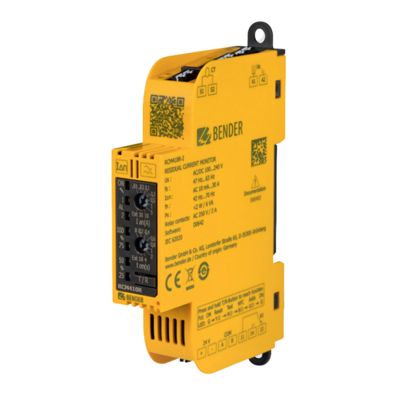
- Page 1 LINETRAXX® RCM410R-1/-2 Single-channel AC and pulsed DC sensitive residual current monitor for AC systems RCM410R-x_D00403_01_M_XXEN/09.2020 Manual EN...
- Page 2 Service and support for Bender products First-level support Technical support Carl-Benz-Strasse 8 • 35305 Grünberg • Germany Telephone: +49 6401 807-760 0700BenderHelp * Fax: +49 6401 807-629 E-mail: support@bender-service.de Available on 365 days from 7.00 a.m. to 8.00 p.m. (MEZ/UTC +1) * Landline German Telekom: Mon-Fri from 9.00 a.m.
-
Page 3: Table Of Contents
Indication of important instructions and information ........5 1.2.1 Signs and symbols ......................5 Training courses and seminars.................5 Delivery conditions .......................5 Inspection, transport and storage ................6 Warranty and liability....................6 Disposal of Bender devices ..................6 Safety ..........................7 Intended use ........................7 Function ....................8 Device features ......................8 Functional description ....................8 2.2.1 Connection monitoring ....................8... - Page 4 Operation and settings on the device ........16 Control panel RCM410R-1/-2 ................. 16 4.1.1 STATUS LED ........................16 4.1.2 ALARM LEDs ......................... 17 4.1.3 VALUE DISPLAY LEDs ....................17 4.1.4 Potentiometer residual operating current I ..........17 Δn 4.1.5 Potentiometer response delay t ................
-
Page 5: General Instructions
Training courses and seminars www.bender.de > Know-how-> Seminars. Delivery conditions The conditions of sale and delivery set out by Bender apply. These can be obtained from Bender in printed or electronic format. The following applies to software products: "Software clause in respect of the licensing of standard software as part of deliveries,... -
Page 6: Inspection, Transport And Storage
• Non-observance of technical data. • Repairs carried out incorrectly. • Use of accessories and spare parts not recommended by Bender. • Catastrophes caused by external influences and force majeure. • Mounting and installation with device combinations not recom- mended by the manufacturer. -
Page 7: Safety
LINETRAXX® RCM410R-1/-2 Safety If the device is used outside the Federal Republic of Germany, the applicable local standards and regulations must be complied with. In Europe, the European standard EN 50110 applies. ! Risk of electrocution due to electric shock! Touching live parts of the system anger carries the risk of: - A fatal electric shock... -
Page 8: Function
Function Function Device features • AC and pulsed DC sensitive residual current monitor type A accord- ing to IEC 62020 • r.m.s. value measurement • Residual operating current: 10 mA…30 A (42…70 Hz) • Prewarning: 50...100 % of the residual operating current • Supply voltage DC 24 V (RCM410R-1) or AC/DC 100…240 V (RCM410R-2) •... -
Page 9: Manual Self Test
LINETRAXX® RCM410R-1/-2 2.2.2 Manual self test By pressing the T/R button > 3 s and < 6 s, the device simulates a residual current with the value 1.5 x I . All LEDs light up and the relay switches. When the fault memory is enabled, the alarm Δn LEDs and the relay remain active until the fault memory is cleared by means of the T/R button. -
Page 10: Factory Settings Fac
Function 2.2.6 Factory settings FAC There are two types of reset: 2.2.6.1 Factory settings without interface After restoring the factory settings, all previously changed settings are reset to the state upon de- livery. The settings for the Modbus interface are not reset. 2.2.6.2 Factory settings with interface After restoring the factory settings, all previously changed settings including the settings for the Modbus interface and the device address are reset to the state upon delivery. -
Page 11: Mounting And Connection
LINETRAXX® RCM410R-1/-2 Mounting and connection Only qualified personnel are permitted to carry out the work necessary to install, com- mission and run a device or system. of electrocution due to electric shock! Touching live parts of the system carries the risk of: - A fatal electric shock - Damage to the electrical installation... -
Page 12: Connection Rcm410R-1/-2
Mounting and connection Connection RCM410R-1/-2 3.2.1 Connections Terminal Connection A1, A2 Supply voltage U S1, S2 Measuring current transformer RCM410R-2 11, 14, 12 Alarm relay K1 +24 V – Ground RS-485 A RCM410R-1 RS-485 B 24 V COM Abb. 3–2 Connections RCM410R–1 and RCM410R–2 The cables are connected to the device via push-in terminals. -
Page 13: Wiring Diagrams
LINETRAXX® RCM410R-1/-2 3.2.2 Wiring diagrams RCM410R-1 RCM410R-2 L1 L2 L3 N L1 L2 L3 N ~/+ ~/– S1 (k) S1 (k) S2 (l) S2 (l) Verbraucher Verbraucher L1 L2 L3 N Load Load ~/+ ~/– +24 V +24 V optional –... -
Page 14: Measuring Current Transformer Connection
Mounting and connection 3.2.2.2 Measuring current transformer connection RCM410R... Measuring current transformer S2(l) S1(k) S2(l) S1(k) Ensure that the measuring current transformers are connected correctly. Terminal S1 must be connected to terminal "S1" (k) of the measuring current transformer. Terminal S2 must be connected to terminal "S2"... -
Page 15: Relay
LINETRAXX® RCM410R-1/-2 L1 L2 L3 N ~/+ ~/– A twisted-pair, shielded cable must be used as bus cable. For example, cable type J-Y(St)Y n x 2 x 0.8 mm² is suitable. The shield must be connected to PE at one end. max. 1 m RS-485 S1 (k) max. -
Page 16: Operation And Settings On The Device
Δn POTENTIOMETER 2 – Response delay t T/R BUTTON – Test/Reset Ext 10 4 ton(s) T / R RCM410R Bender Control panel RCM410R-1/-2 4.1.1 STATUS LED Multicoloured display of various operating modes. Operating mode START PHASE GREEN Device booting after start... -
Page 17: Alarm Leds
50 % of I Δn RCM410R Lights permanently when the present measured value is Ext 10 4 above 75 % of I Δn Bender Lights permanently when the present measured value is ton(s) above 100 % of I Δn T / R RCM410R Bender 4.1.4 Potentiometer residual operating current I... -
Page 18: Potentiometer Response Delay T
10 s to 15 s flashes green Addr. Bender Overview The NFC mode is available to the Bender service only. 4.1.6.1 "Reset" function The "Reset" function resets stored alarm states. 4.1.6.2 "Test" function The "Test" function simulates a residual current of 1.5 x I for a period of Δn... -
Page 19: Nfc" Function
LINETRAXX® RCM410R-1/-2 4.1.6.3 "NFC" function The "NFC" function can be enabled or disabled. This function is for service purposes only. The NFC function is enabled by pressing the T/R button for a period of 6 s to 10 s. The status LED indicates when the NFC function is enabled. -
Page 20: Modbus Settings
Modbus settings Modbus settings Overview Description of the Modbus registers for RCM41x devices. The following Modbus function codes are supported: • Holding register for reading out values Status LED (Read Holding Register; function code 0x03) • Register for device programming (Write Multiple Registers;... -
Page 21: Register Table
String UTF8 e.g.: B74602000 (RCM410R-1) B74603000 (RCM410R-2) Serial number String UTF8 10 digits e.g.: 2002123456 Manufacturer String UTF8 Bender GmbH & Co. KG Application D number Uint16 642 = D642 Application version number Uint16 xxx = Vx.xx Application build number... - Page 22 Modbus settings Address Register name Data type Bytes Mode Value/Unit/Comment Factory (dec) setting Modbus RTU parameters (32000…32099) 32000 Device address Uint16 1…247 Last 2 digits of the serial number + 32001 Baud rate Uint32 9600, 19200, 38400, 57600, 115200 19200 32003 Parity Uint16...
- Page 23 LINETRAXX® RCM410R-1/-2 Address Register name Data type Bytes Mode Value/Unit/Comment Factory (dec) setting Device error codes (58000…58999) 58000 Number of device errors Uint16 Number of active device errors 58001 Uint16 58002 Uint16 58003 Uint16 0 = no device error 58004 Uint16 Internal device error >...
- Page 24 Modbus settings Address Register name Data type Bytes Mode Value/Unit/Comment Factory (dec) setting Function 4: Reset to factory settings/Reset parameters 4 → Selection of "Reset to factory 60000 Function selection Uint16 settings/Reset parameters" function 62663 → Safety pattern must be written 60001 Pattern value part 1 Uint16...
-
Page 25: Error - Cause - Error Correction
LINETRAXX® RCM410R-1/-2 Error – Cause – Error correction Error pattern Cause Correction Source RS-485 Unstable system Missing termination due to incorrect Configure the terminating resistor, determine commissioning or defective component. the terminating resistor value and replace it if No device is terminated. necessary. -
Page 26: Technical Data
Technical data Technical data * = factory setting Insulation coordination acc. to Supply voltage IEC 60664-1/IEC 60664-3 RCM410R-1: RCM410R-1: Supply voltage U .............DC 24 V Definitions: Tolerance of U ............-30…+25 % Power consumption ............≤ 2 W Measuring & control circuit (IC1) ......S1, S2, +, –, A, B Inrush current (<... -
Page 27: Standards & Certifications
LINETRAXX® RCM410R-1/-2 Displays, memory Classification of climatic conditions acc. to IEC 60721 (ex- Display ........status LED incl. LED bar graph cept condensation and formation of ice) Display range measured value ........0…100 % Stationary use (IEC 60721-3-3) ..........3K23 Fault memory alarm messages ....... on/off (on)* Transport (IEC 60721-3-2) ...........2K11 Long-term storage (IEC 60721-3-1) ........1K22 Cable lengths for measuring current trans-... - Page 28 Nachdruck und Vervielfältigung Reprinting and duplicating nur mit Genehmigung des Herausgebers. only with permission of the publisher. Bender GmbH & Co. KG Bender GmbH & Co. KG Postfach 1161 • 35301 Grünberg • Deutschland PO Box 1161 • 35301 Grünberg • Germany Londorfer Str.
Need help?
Do you have a question about the LINETRAXX RCM410R-1 and is the answer not in the manual?
Questions and answers