
Related Manuals for Bender RCMA426H


Summary of Contents for Bender RCMA426H
- Page 1 Manual RCMA426H Residual current monitor for monitoring AC, DC and pulsed DC currents in earthed and resistance earthed systems Software version D309 V1.0x RCMA426_D00065_00_M_XXEN/05.2014...
- Page 2 Bender GmbH & Co. KG P.O. Box 1161 • 35301 Gruenberg • Germany Londorfer Str. 65 • 35305 Gruenberg • Germany Tel.: +49 6401 807-0 Fax: +49 6401 807-259 E-Mail: info@bender.de Web: http://www.bender.de © Bender GmbH & Co. KG All rights reserved.
-
Page 3: Table Of Contents
Table of Contents 1. Effective use of this manual ................5 Notes for the user ..................... 5 Intended use ...................... 5 2. Safety instructions ................... 7 General safety instructions ................7 Work activities on electrical installations ..........7 3. Function ......................9 Device features .................... - Page 4 Data RCMA426H-D-2 in table form ............27 Error codes ....................... 30 Recommended contactors ................ 31 Response times of the RCMA426H system plus contactor in ac- cordance with UL943 ................... 32 Ordering information ................... 33 Standards, approvals and certifications ..........33 INDEX ........................
-
Page 5: Effective Use Of This Manual
Info symbol. 1.2 Intended use The AC/DC sensitive residual current monitor RCMA426H with its measuring current transformer WN-35BS is used to monitor earthed and resistive- earthed systems (TN and TT systems) in which DC and AC fault currents may occur. - Page 6 Effective use of this manual RCMA426_D00065_00_M_XXEN/05.2014...
-
Page 7: Safety Instructions
2.1 General safety instructions In addition to these operating instructions, the "Important safety instructions for Bender products“, which are also included in the scope of supply, are an in- tegral part of the device documentation. 2.2 Work activities on electrical installations Only skilled persons are permitted to carry out the work necessary to ... - Page 8 Safety instructions RCMA426_D00065_00_M_XXEN/05.2014...
-
Page 9: Function
3.2 Function The RCMA426H runs a device test when the power supply voltage is connect- ed. During the start-up phase, the TRP LED lights up, the alarm LED ERR flashes and the alarm relay switches to the alarm setting. -
Page 10: Transformer Monitoring
Function The device will check the circuit for the presence of residual currents even dur- ing the self test. An internal measuring current transformer is used for residual current meas- urement. The actual measured value is indicated on the LC display. If the rated residual operating current of 6 mA is exceeded, the alarm relay K2 will change to the alarm state and the TRP alarm LED will light up. -
Page 11: Self Test, Automatic
Function 3.2.3 Self test, automatic The device runs a self test every 24 h. Any internal malfunctions detected are shown on the display as error codes. The automatic self test is carried out without internal fault current. The alarm relay is not switched during the 24-h test. -
Page 12: Factory Setting Fac
Function 3.2.7 Factory setting FAC Activating the factory setting will reset all modified settings, with the excep- tion of the device address, to the default upon delivery. 3.2.8 Erasable history memory HiS The first alarm value to occur is written to this memory. The memory can be erased via the menu HiS. -
Page 13: Installation And Connection
4.1 Dimension diagrams RCMA426H dimension diagram and drawing for screw fixing The front plate cover is easy to open at the lower part marked by an arrow. Dimensions in mm... - Page 14 Installation and connection 1. Mounting on a DIN rail: Snap the mounting clip at the rear of the device onto the DIN rail so that it sits securely. Screw fixing: Using a tool, position the rear mounting clips (a second mounting clip is required, see the ordering information) so that it protrudes over the enclosure.
-
Page 15: Factory Setting
Installation and connection Key to wiring diagram Terminal Connections A1, A2 Connection to the power supply T1, T2 Test connections for internal monitoring circuit T, T/R, R Connections for external test and reset button 21, 22, 24 Alarm relay K2: Connection to contactor or load switch CT Internal measuring current transformer: D = 13 mm K1 Recommended contactors are listed in the table on page 31 4.2 Factory setting... - Page 16 Installation and connection RCMA426_D00065_00_M_XXEN/05.2014...
-
Page 17: Operation And Configuration
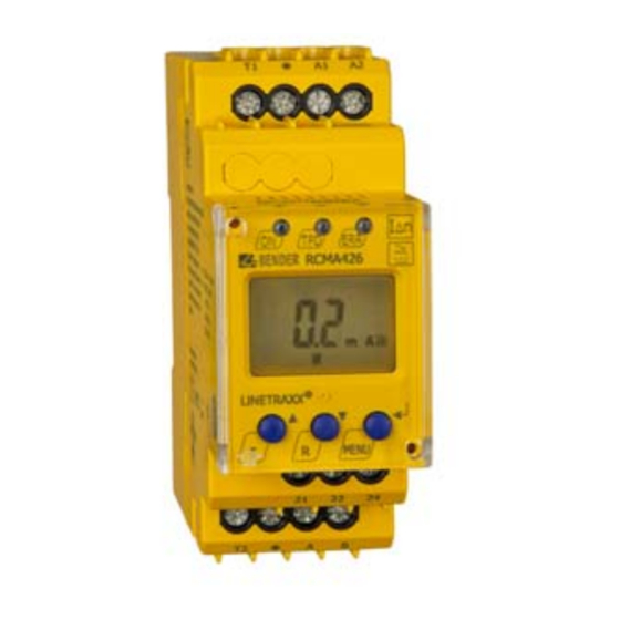
5. Operation and configuration 5.1 Getting to know the user interface Green Power ON LED: Lights up when the power supply volt- age is connected and the device is run- ning. Red TPD alarm LED: Lights up when the rated residual op- erating current I is exceeded. -
Page 18: Understanding Information On The Standard Display
Operation and configuration 5.2 Understanding information on the standard display Fig. 5.1: Standard Measured value display in mA: Current type display AC / DC Password protection activat- Fault memory activated The actual measured residual current is displayed by default. Press the Up or Down button to display the factory-set rated residual operat- ing current I . -
Page 19: Getting To Know Buttons And Button Functions
Operation and configuration 5.3 Getting to know buttons and button functions The table below lists the functions of the buttons when navigating through the display, navigating through the menu and when making settings. From "chapter 5.7 Making settings in the menu" in the menu onwards, just the rele- vant button symbol is used to indicate that buttons have been pressed. -
Page 20: Starting A Manual Self Test
Operation and configuration 5.4 Starting a manual self test You can start a self test manually. During the test, any internal malfunctions detected are shown on the display as error codes. The alarm relay will be switched. To start a self test manually: Press and hold down the test button T (UP) or external test button ... -
Page 21: Making Settings In The Menu
Operation and configuration 5.7 Making settings in the menu 5.7.1 Selecting menus Press and hold down the MENU button for more than 1.5 seconds to call up the menu. Menus are available for a variety of settings. In turn, each menu has a number of submenus. -
Page 22: Querying The Software Version With The Inf Menu
Operation and configuration 5.7.2 Querying the software version with the InF menu 1. Select the InF menu 2. Confirm with Enter The software version (e.g.: d309-1.00) is displayed as running text. Once all in- formation is showing on the display, you can use the UP/DOWN buttons to se- lect individual items. - Page 23 Operation and configuration Change Change/activate/ Change/apply SEt menu Select submenu parameter deactivate param. param. value display 2. Change pass- word 3. Deactivate password protection 4. Switch sub- menu RCMA426_D00065_00_M_XXEN/05.2014...
-
Page 24: Querying And Erasing The Fault Memory In The His Menu
Operation and configuration Change Change/activate/ Change/apply SEt menu Select submenu parameter deactivate param. param. value display 5. Restore factory set- ting "run" appears on the display and the device is reset to the factory settings automatically. 6. Switch submenu 7. System menu (is locked) 8. - Page 25 Operation and configuration HiS menu Error display/Submenu 1. Error: Rated residual operating cur- rent exceeded 2. Switch error display 3. Error code E.03 see page 30 4. Switch error display 5. Erase fault memory 6. Switch error display 7. Go back to HiS menu RCMA426_D00065_00_M_XXEN/05.2014...
- Page 26 Operation and configuration RCMA426_D00065_00_M_XXEN/05.2014...
-
Page 27: Technical Data
6. Technical data 6.1 Data RCMA426H-D-2 in table form ( )* = factory setting Insulation coordination acc. to IEC 60664-1 / IEC 60664-3 Rated insulation voltage ............................250 V Overvoltage category/ pollution degree........................III/3 Rated impulse voltage.............................. 4 kV Protective separation (reinforced insulation) between........... (A1, A2) - (k/l, T/R) - (21, 22, 24) Voltage tests according to IEC 61010-1...................... - Page 28 Technical data Displays, memory Display range. AC/DC measured value ......................0…40 mA Resolution of setting ............................0.1 mA Error of indication 0…20 Hz ..................-33 %…+100 % / ± 2 digits Error of indication 20…90 Hz ....................0…20% / ± 2 digits Error of indication 90…150 Hz ....................
- Page 29 Technical data Connection For UL application.................... use 60°C/70°C copper conductors only Connection type ..........................screw terminals rigid/ flexible/ conductor sizes ..............0.2…4 / 0.2…2.5 mm / AWG 24…12 Multi-conductor connection (2 conductors with the same cross section) Rigid, flexible ........................0.2…1.5 / 0.2…1.5 mm Stripping length ............................
-
Page 30: Error Codes
Appropriate action when error codes > 04 occur: Action: E…. Perform a reset. Restore the device to the factory setting. Should the error persist, contact Bender Service. The error code will be erased automatically once the error has been eliminated. RCMA426_D00065_00_M_XXEN/05.2014... -
Page 31: Recommended Contactors
Technical data 6.3 Recommended contactors The ABB types listed below have undergone performance testing: Auxilary contact Main contact Contactor type A16-30-10-84 A26-30-10-84 A40-30-10-84 A75-30-00-84 A110-30-00-84 A145-30-00-84 A16-30-10-34 A26-30-10-34 A40-30-10-34 A75-30-00-34 A110-30-00-34 A145-30-00-34 A16-40-00-84 A26-40-00-84 A45-40-00-84 A75-40-00-84 EK150* -40-22 A16-40-00-34 A26-40-00-34 A45-40-00-34 A75-40-00-34 EK150** -40-22... -
Page 32: Response Times Of The Rcma426H System Plus Contactor In Accordance With Ul943
Technical data 6.4 Response times of the RCMA426H system plus contactor in accordance with UL943 RCMA426_D00065_00_M_XXEN/05.2014... -
Page 33: Ordering Information
AC 42…460 Hz Art. No.: with screw terminal B 9404 3021 with push-wire terminal B 7404 3021 *Absolute values of the voltage range RCMA426H accessories Mounting clip for screw fixing (1 per device)................... B 9806 0008 6.6 Standards, approvals and certifications RCMA426_D00065_00_M_XXEN/05.2014... - Page 34 Technical data RCMA426_D00065_00_M_XXEN/05.2014...
-
Page 35: Index
INDEX Accessories 33 Installation and connection 13 Automatic self test 11 Manual self test 20 Button functions 19 Manual, target group 5 Menu, settings 21 Multi-conductor connection 29 Calling up the menu 20 Commissioning 15 Notes for the user 5 Device features 9 Device test 9 Operation and configuration 17... - Page 36 Recommended contactors 31 Response times 32 Restore factory setting 24 screw terminals 29 Self test, manual 11 SEt menu 22 Technical data 27 Wiring diagram 14 Work activities on electrical installations 7 RCMA426_D00065_00_M_XXEN/05.2014...
- Page 37 RCMA426_D00065_00_M_XXEN/05.2014...
- Page 38 RCMA426_D00065_00_M_XXEN/05.2014...
- Page 40 D0006500MXXEN Bender GmbH & Co. KG P.O. Box 1161 • 35301 Gruenberg • Germany Londorfer Str. 65 • 35305 Gruenberg • Germany Tel.: +49 6401 807-0 Fax: +49 6401 807-259 E-Mail: info@bender.de Web: http://www.bender.de...
Need help?
Do you have a question about the RCMA426H and is the answer not in the manual?
Questions and answers