Table of Contents
Advertisement
Quick Links
Download this manual
See also:
User Manual
Advertisement
Table of Contents

Subscribe to Our Youtube Channel
Related Manuals for Vemco VR100


Summary of Contents for Vemco VR100
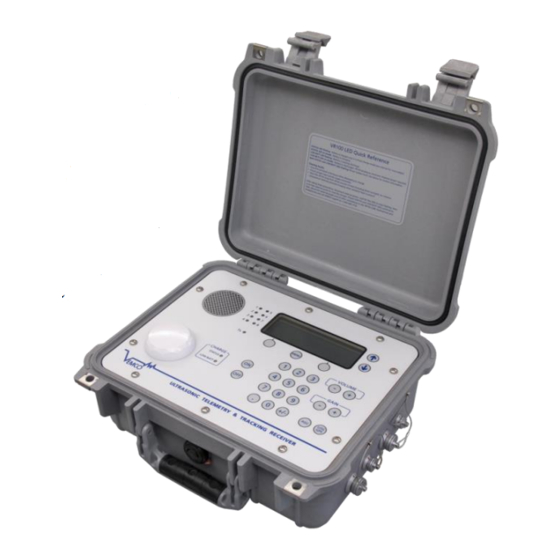
- Page 1 VR100 RECEIVER OPERATING MANUAL DOC-4536-13 December 13, 2012 VEMCO, a Division of AMIRIX Systems Inc.
- Page 2 VEMCO’s liability, and the Buyer’s exclusive remedy under this warranty, as to a defect in material or workmanship, is limited to the repair of such defect in the accessory, equipment or part in which the defect appears or, at VEMCO’s option, to the replacement of such accessory, equipment or part with a similar item free from defect. As to any item repaired by VEMCO or furnished as a replacement by VEMCO, VEMCO’s liability and the Buyer’s exclusive remedy to the repair or replacement of such item for any further defect in material or workmanship,...
- Page 3 Set the volume to a safe level. Avoid turning up the volume to block out noisy surroundings. Warning If the VR100 is not used in the manner specified by the manufacturer, protection may be impaired.
-
Page 4: Table Of Contents
Connectors..........................18 3.1.2.1 Using connectors ......................18 3.1.2.2 Using protective caps ....................... 19 3.1.3 VR100 Front panel ........................20 3.1.3.1 VR100 Front panel Explanations ..................21 ..........................22 TTACHMENTS 3.2.1 Hydrophone ..........................22 3.2.2 USB Cable ..........................23 3.2.3 Headphones ..........................24 .......................... - Page 5 APPENDIX ............................47 ......................47 DDITIONAL INFORMATION 5.1.1 GPS ............................47 ......................49 ETECTION ARAMETERS ............................50 LOSSARY ........................51 ROUBLESHOOTING VR100 H ....................... 52 ARDWARE ERSIONS ..........................53 PECIFICATIONS ......................53 LEANING NSTRUCTIONS ........................ 54 ONTACT NFORMATION INDEX ..............................55...
-
Page 6: Introduction
The VR100 can detect continuous and coded tags on eight separate frequencies and at the same time. It can also store the detections, along with the date/time and GPS location of the receiver at the time of the detection, to be loaded to a computer for viewing or analysis. -
Page 7: Using This Manual
This manual, the VR100 Operating Manual, contains the necessary information to care for the VR100 receiver and use it as a stand-alone unit. The receiver can be connected to a computer running the VR100 software and the necessary details are contained in the VR100 Software manual. -
Page 8: Applications
2 APPLICATIONS 2.1 QUICK SETUP The list below gives the order of actions needed to set up and use the VR100 receiver. The steps may reference sections in this manual that contain more details about that step. Open the lid of the VR100 case (see section 3.1.1). -
Page 9: Common Applications
COMMON APPLICATIONS This section contains steps needed to perform common tasks on the VR100 receiver. The steps are referenced to sections in the manual that contain more information on the topic. 2.2.1 Set up a channel to monitor a continuous pinger A channel can be set up to monitor continuous pingers operating on the same frequency. -
Page 10: Set Up A Channel To Monitor A Coded Tag
NOTE: The tag must be set up in the receiver before it can be monitored. See section 4.3.4.2 or 4.3.4.3 for how to set up a continuous sensor transmitter in the VR100 receiver. Review the summary screen to verify that the information is correct. -
Page 11: Manually Tracking A Continuous Pinger
2.2.4 Manually tracking a continuous pinger After a channel in the VR100 has been setup to detect the continuous pinger (see section 4.3.1.2.1) and the pinger has been deployed, use the steps below to use the VR100 to track the pinger. -
Page 12: Manually Tracking A Coded Tag
2.2.5 Manually tracking a coded tag After a channel in the VR100 has been setup to detect the coded pinger (see section 4.3.1.2.2) and the pinger has been deployed, use the steps below to use the VR100 to track the pinger. -
Page 13: Enter Slope And Intercept For A Continuous One-Sensor Transmitter
2.2.6 Enter slope and intercept for a continuous one-sensor transmitter The tag’s information that must be entered in the VR100 is found in the Transmitter Specification manual shipped with the tags. See section 4.3.4 for more details. From the Main menu: Select Config (right selection button). -
Page 14: Enter Slope And Intercept For A Coded Sensor Tag
Press the Menu button until the Main screen appears. 2.2.8 Enter slope and intercept for a coded sensor tag The tag’s information that must be entered in the VR100 is found in the Transmitter Specification manual shipped with the tags. See section 4.3.4.1 for more details. -
Page 15: Take A Gps Reading
2.2.10 View Used Memory Level The Use line in the Event Log screen shows the percentage of log memory used in the VR100 receiver, both numerically and graphically. When 100 % of the log memory is full, the memory must be erased before more events can be logged;... -
Page 16: Clear Vr100 Memory
Confirm the erasure of the data by pressing the button identified in the confirmation window. Erasing the event log will only erase the events that have occurred to the VR100 receiver and not the channel settings or the sensor tag information. -
Page 17: Hardware
To open the VR100 case, follow the steps below. Place the case on a stable, flat, horizontal surface so the VR100 label is on the top (facing up). Lift one of the latches (see photo below) until it is horizontal. The latch will separate slightly as it is moved, as the right latch shows in the photo below. -
Page 18: Connectors
There are four bulkhead connectors on the right side of the VR100 case for connecting the different components of the VR100 system to the receiver (see photo below, on the left). The connectors are, from left to right: hydrophone, PC connection, battery charger, and headphone. -
Page 19: Using Protective Caps
3.1.2.2 Using protective caps The connector’s protective cap is used to prevent water from entering the connector and damaging the connector and possibly the receiver. With the cap properly in place, the VR100 is extremely splash- resistant. To properly install a connector protective cap: 1. -
Page 20: Vr100 Front Panel
3.1.3 VR100 Front panel The VR100 receiver’s front panel allows the VR100 to be configured and allows deployed tags to be monitored. The panel uses soft press keys for all its data entry and controls, increasing the receiver’s ability to operate in a moist environment. The soft buttons are easy to wipe clean but still give the user a “click”... -
Page 21: Vr100 Front Panel Explanations
60 kHz. C) LCD screen and three related buttons: The LCD screen is used to monitor tags and to configure the VR100. The use of the screen and the three buttons immediately below it is explained in section 4. -
Page 22: Attachments
3.2 ATTACHMENTS 3.2.1 Hydrophone The hydrophone can be compared to a human ear where the VR100 is the human brain. Our ear hears the noises around us and transfers them to the brain where the noises are analyzed and identified. The hydrophone hears pings from acoustic tags in the water, as well as other noises in the environment such as current flow, marine animals, and ship engines. -
Page 23: Usb Cable
USB cable, shown in the photo here. The marine grade connector, shown on the left in the photo, is connected to the second connector from the left on the VR100 case (see section 3.1.2) and the USB connector, shown on the right in the photo, is connected to a USB port on the computer. -
Page 24: Headphones
3.2.3 Headphones A marine grade headphone jack is located on the side of the VR100 case (see section 3.1.2). A pair of headphones with a matching jack is supplied by VEMCO. WARNING: Do not allow the headphone connector to come in contact with water. Water could enter the back of the connector and damage the headphone cable, which could potentially damage the VR100 receiver. -
Page 25: Maintenance
Operating time with the backlight on is shorter. The VR100 can also be powered while the battery is being charged, allowing the receiver to continue to operate during the charging process. -
Page 26: Charge Indicator Lights
NOTE: The VR100 battery can be left in Float Charge mode for an extended period of time without causing damage to the battery, but the receiver’s front panel must be facing up. A sensor is included in the VR100 that prevents the receiver from being charged while the receiver is at a steep angle or upside down. -
Page 27: Maximizing Battery Service Life
A series of partial discharges is gentler on the battery than a deep discharge. If the VR100 shuts itself down due to a fully discharged battery, do not turn it back on until you have connected the charger. -
Page 28: Operation
6. VERSION 7. RESET DEF When the VR100 is powered, the welcome screens appear while the receiver is booting up. After the boot process is complete, the Main menu appears in the LCD screen. From the Main menu, there are two selection options, Monitor and Configure (Config). -
Page 29: Main Menu
The LCD screen on the VR100 receiver has four lines for text, and each line may contain more than one piece of information. The information found on the Main menu, and the buttons used with the screen, are identified in the sketch and described below. - Page 30 GPS status. The different status messages are explained in the Appendix (section 5.1.1). GPS status line 2: The number of satellites in view and SBAS indicator are shown on this line. Note that SBAS is supported only on model VR100-200 VEMCO – VR100 Receiver Operating Manual – Page 30...
-
Page 31: Monitor
(0dB = minimum measureable voltage, 105dB = full scale voltage). It is strictly a relative measure of signal strength and cannot be used to measure the output power of a transmitter in terms of dB re 1uPa @ 1m. VEMCO – VR100 Receiver Operating Manual – Page 31... - Page 32 AGC button on the front panel of the receiver (see section 3.1.3). NOTE: Since the VR100 receiver has a wide dynamic range, the gain setting is not critical in most situations. A good setting for general use is to set the gain manually to 12 dB. If the reported signal strength is consistently greater than 90 dB, reduce the manual gain setting.
-
Page 33: Configure
999 to indicate there haven’t been recent detections. 4.3 CONFIGURE The Configure section of the VR100 receiver allows the receiver to be configured according to a user’s needs. This includes setting up tags, selecting code maps, setting up channels, turning channels on and off, adjusting the contrast, turning on the backlight, and setting the units. -
Page 34: Channel (1)
Configure main menu by 3 Code Maps pressing the “2” button and then the “3” button on the keypad. The menu numbers are Select included in the previous map for easy reference. VEMCO – VR100 Receiver Operating Manual – Page 34... -
Page 35: Enable A Channel
60 kHz. Another channel can be configured to listen for coded tags operating at 69 kHz. There are eight channels in the VR100 receiver which means that the receiver can monitor eight different configurations at one time. -
Page 36: Configure A Channel For A Continuous Pinger
Select the code map (see section 4.3.3) to be used on this channel and then select “Next”. To use a non-standard map, the map must be imported using the PC software before a channel can be configured to use that map. VEMCO – VR100 Receiver Operating Manual – Page 36... -
Page 37: Configure A Channel For Continuous Sensor Transmitters (1 Or 2 Sensors)
Select the desired channel number on the keypad and press the right selection button for “Configure”. The channel’s configuration is displayed in a summary screen. Select “Accept” (right selection button) to return to the Channel window without making changes to the channel’s configuration. VEMCO – VR100 Receiver Operating Manual – Page 37... -
Page 38: System (2)
VEMCO is located in the Atlantic Standard Time zone, which is four hours behind UTC. The offset value “– 4” must be entered in the VR100 for the receiver to display the time at VEMCO. Samples of UTC conversions are listed in Table 4.3-1. -
Page 39: Contrast (2-2)
4.3.2.2 Contrast (2-2) The contrast between the text and the background on the VR100’s screen can be adjusted. The contrast should be set so the text on the screen is clearly visible without any of the background lines being visible. -
Page 40: Backlight (2-3)
NOTE: If an external power source is connected to the receiver, then the voltage reported by the VR100 is the voltage of the external power supply and not the internal battery. Turn off the receiver, unplug the external power supply, and turn the VR100 on to read the battery voltage with the steps below. -
Page 41: Version (2-6)
VEMCO. 4.3.2.7 Reset to Factory Defaults (2-7) The Reset to Factory Defaults option will return the VR100 to the factory default settings, removing all sensor transmitters from the tag database and clearing the channel configurations. A confirmation window will appear to verify that this is the desired action before the receiver is reset. -
Page 42: Code Maps (3)
4.3.3.1 Understanding Code Maps There are three default code maps used with VEMCO coded tags, MAP-113 for 69 kHz, MAP-413 for 180 kHz and MAP-311 for 81 kHz. These maps are installed by default. Several legacy maps can be installed on the receiver using the VR100HS PC Software, but should only be used if directed by Vemco Customer Support. -
Page 43: Sensor Transmitters (4)
Coded, Cont One, and Cont Two. NOTE Only tags with When the VR100 has 750 tags setup, meaning the tag storage capabilities are full, a sensors need new tag can’t be entered until an existing tag is deleted. To delete a tag, first... -
Page 44: Setting Up One-Sensor Continuous Sensor Transmitters (4-2)
NOTE: For coded two-sensor tags, two separate sensor tag entries are required – one for each tag ID (sensor). Since the VR100 does not allow duplicate serial numbers in the sensor database, the serial number for the second sensor entry must be different than the first sensor entry. We recommend that you use the serial number provided on the specification sheet for the first sensor entry, and the same serial number with a prefix for the second sensor entry. -
Page 45: Log (5)
The number of events increases until the memory is full at approximately 85000 events. The Use line in the Event Log screen shows the percentage of log memory used in the VR100 receiver, both numerically and graphically. When 100 % of the log memory is full, the memory must be erased before more events can be logged. - Page 46 The event log memory is erased by first pressing the right selection button. A confirmation window appears before the log is erased so the log can’t be accidentally erased. Erasing the event log will only erase the events that have occurred to the VR100 receiver and not the channel settings or the sensor tag information.
-
Page 47: Appendix
X is a digit (0-9), A is N (North) or S (South), and B is E (East) or W (West). When the VR100 is not locked, the GPS message displayed will be one of those listed in Table 5.1-1. The status of the GPS is updated every 5 seconds. - Page 48 EGNOS (Europe) MSAS (Japan) The VR100 will utilize SBAS if the signal is detected, and this will be indicated by displaying “SBAS” on the third line of the main menu screen. This feature is not supported by the VR100-100 hardware version.
-
Page 49: Detection Parameters
The detection parameter levels are used to determine how a real signal, referred to as a detection, is distinguished from background noise. The VR100 constantly receives a signal similar to the one shown in the drawing below. This usually includes a large amount of background noise from sources such as noises in the hydrophone’s environment, electronic components in the receiver, etc. -
Page 50: Glossary
The Blanking Interval is the length of time (in milliseconds) after an acoustic signal has been received on a given channel in which the VR100 will ignore any subsequent signals on that same channel. This is to eliminate the reception of echoes by the receiver. -
Page 51: Troubleshooting
A low PDOP indicates the satellites are nicely arranged to give a good position. The PDOP may be improved by facing the VR100 GPS antenna towards the equator where more satellites are located. -
Page 52: Vr100 Hardware Versions
There are two major versions of the VR100 hardware covered by this manual, VR100-100 and VR100- 200. You can identify the hardware version of your VR100 by observing the nameplate label and the GPS antenna. Both models provide the same acoustic receiver functionality, but VR100-200 has a new GPS and antenna with improved performance specifications and support for WAAS, EGNOS and MSAS augmentation for enhanced accuracy. -
Page 53: Specifications
Overlay Service; MSAS=Multi-functional Satellite Augmentation System 5.7 CLEANING INSTRUCTIONS Clean VR100 with a damp cloth and mild detergent. Do not use solvents. Do not use abrasive cleaners. Do not allow oils, resins, paints, or similar gummy materials to enter the case vent – these can clog the vent and prevent it from operating properly, possibly creating a safety hazard. -
Page 54: Contact Information
5.8 CONTACT INFORMATION Product manufactured by VEMCO Division AMIRIX Systems Inc. 211 Horseshoe Lake Drive Halifax, Nova Scotia Canada B3S 0B9 Phone: +1-902-450-1700 Fax: +1-902-450-1704 Web Site: www.vemco.com Email: support@vemco.com VEMCO – VR100 Receiver Operating Manual – Page 54... -
Page 55: Index
Sensor Transmitter, 7, 9, 13, 33, 51 Gain control, 21 Units, 8, 40 LCR screen, 21 USB cable, 23 Volume control, 21 UTC, 29, 38, 50 Gain, 8, 16, 21, 32, 50 VEMCO – VR100 Receiver Operating Manual – Page 55...
Need help?
Do you have a question about the VR100 and is the answer not in the manual?
Questions and answers