
Subscribe to Our Youtube Channel
Related Manuals for Vemco VR100


Summary of Contents for Vemco VR100
- Page 1 How to use the VR100 receiver – as a manually tracking receiver and as a transponding deckbox. www.vemco.com 24 May 2018 DOC-4536-18...
- Page 2 How to care for the equipment and prepare it for storage Section 6: Additional Information Additional information about the VR100 that is good to know but not mandatory for basic operations Section 7: Common Questions Answers to frequently asked questions related to using the VR100 receiver...
-
Page 3: Table Of Contents
Setup a Channel for Transponding ................18 2.3.5 Turn a Channel ON ....................19 Testing ..........................19 3 Software ................20 Install VR100 PC software ....................20 Connect to VR100 ......................20 VR100 Receiver Window ....................21 Offload Data ........................22 3.4.1 Get All Data ...................... - Page 4 6.1.1 VR100 Main Screen....................43 6.1.2 Configure Menu Structure ..................44 6.1.2.1 Entering Configure menu ..................45 6.1.2.2 Transponding Settings in the VR100-200 .............. 45 6.1.2.2.1 Hydrophone ........................45 6.1.2.2.2 Auto Scanning ........................45 6.1.2.2.3 Reset Session ........................46 6.1.2.2.4 Logging ..........................
- Page 5 What is an event and how do I know if I have any? ..........77 VR100 PC Software Related Questions ................77 How do I load the VR100’s tag setup to the PC? ............77 7.3.1 Transponding Related Questions ..................78 I can’t communicate with the receiver.
- Page 6 Set the volume to a safe level. Avoid turning up the volume to block out noisy surroundings. WARNING If the VR100 is not used in the manner specified in this manual, then the manufacturer's warranty protection may be voided.
-
Page 7: Introduction
Receivers also report the slant (or absolute) distance between the receiver and the transponding hydrophone connected to the VR100. The VR2AR, with its depth sensor, can also report its depth and the horizontal distance between it and the transponding hydrophone. -
Page 8: Quick Setup
1.2 Quick Setup The list below gives the order of actions needed to set up and use the VR100 receiver. The steps may reference sections in this manual that contain more details about that step. Connect the hydrophone to the bulkhead connector on the side of the case (see section 2.1.1). -
Page 9: Vr100 Case
There are two major versions of the VR100 hardware covered by this manual, VR100-100 and VR100-200. You can identify the hardware version of your VR100 by observing the nameplate label, as shown in the pictures included in the table below. -
Page 10: Case Parts
headphones These components are all connected to the VR100 through connectors on the side of the case. The case has a pressure relief vent to allow any pressure build-up in the case to release before the case is opened. A manufacture’s tag is attached to the vent and should not be removed. Removing the tag may damage the vent. -
Page 11: Connectors And Caps
1.5 Connectors and Caps There are four bulkhead connectors on the right side of the VR100 case that are used to connect the different components of the VR100 system to the receiver, such as the hydrophone. The picture below shows the connectors without their protective caps in place. -
Page 12: Inserting A Connector
1.5.2 The red dot on the end of the connector must line up with the red line on the VR100’s connector, as shown in the photo on the right. The connectors have unique grooves to prevent the wrong connector halves from being placed together. -
Page 13: Vr100 Front Panel
VR100 Front Panel 1.5.4 The VR100 receiver’s front panel allows the VR100 to be configured, allows deployed tags to be monitored, and allows two-way acoustic communication with transponding receivers like the VR2AR – including sending the release command. The panel uses soft press keys for all its data entry and controls, increasing the receiver’s ability to operate in a moist environment. -
Page 14: Vr100 Screen
1.5.5 The LCD screen on the VR100 receiver has four lines for text and changes based on the task at hand. The Main Screen is shown below and appears when the VR100 is turned on. The buttons used with the screen are identified and described in the sketch below. - Page 15 (VR2AR only). only) Regardless of the hydrophone being used, it is connected to the VR100 through the bulkhead connector on the side of the receiver (see section 2.1.1). VEMCO – VR100 Manual...
-
Page 16: Usb Cable
VR100 receiver. Headphones 1.6.3 A marine grade headphone jack is located on the side of the VR100 case (see section 1.5). A pair of headphones with a matching jack can be purchased from VEMCO. WARNING Permanent hearing loss may occur if the headphones or internal speaker is used at high volume. -
Page 17: Getting Started
2.1 Setup VR100 There are some basic things that should be done before the VR100 is used, such as setting the time offset, selecting units used for sensor tags, verifying the code map you require, and entering sensor tag information. - Page 18 WARNING DO NOT get water in the connectors on the cables that attach to the VR100 receiver, such as the PC connection cable or the headphone cable. Water will enter the connector to damage the cabling and potentially damage the receiver.
-
Page 19: Set Local Time Offset
Press “1” on the keypad. Enter the UTC offset for the area where the VR100 will be used (see section 6.7) on the keypad. This is a number between –12.0 and +12.0. The negative, if needed, must be entered before the number or the number will be erased and have to be re-entered. -
Page 20: Verify Code Maps
OFF option. The backlight should only be needed indoors and at night. Operating the VR100 with the backlight on will greatly reduce the operating time between battery charges. The SMART option leaves the backlight off if the keypad is inactive but will turn the backlight on for five seconds when a button is pressed on the keypad. -
Page 21: Enter Tag Information
Coded, Cont One, and Cont Two. When the VR100 tag storage capabilities are full, a new tag can’t be entered until an existing tag is deleted. To delete a tag, first highlight the tag by either scrolling through the list of entered serial numbers or by entering the serial number on the keypad. -
Page 22: Setup A Continuous Sensor Tag
Press the Menu button until the Main screen appears. 2.3 Setup Channels A channel in the VR100 is a group of configuration settings used to listen to VEMCO tags. For example, a channel can be configured to listen for continuous pingers that operate at 60 kHz. -
Page 23: Setup A Channel To Monitor A Continuous Sensor Tag
NOTE: The tag must be set up in the receiver before it can be monitored. See section 2.2.2 or 3.8.1 for how to set up a continuous sensor transmitter in the VR100 receiver. Review the summary screen to verify that the information is correct. -
Page 24: Setup A Channel To Monitor A Coded Tag
Setup a Channel for Transponding 2.3.4 The transponding process uses Channel 8 to receive communication from the receiver. VR100 receivers shipped after March 2015 have Channel 8 setup for transponding by default, but if your receiver is slightly older or the channel setup have been altered, then follow the steps listed below to setup the channel correctly. -
Page 25: Turn A Channel On
2.4 Testing Perform air tests away from Before deploying tags, it is wise to test them with the VR100 to verify the electrical noise sources such tags are operating properly and the VR100 is setup to detect them. as motors, PC screens, or 1. -
Page 26: Software
After the software is installed connect a VR100 receiver to the PC using the supplied USB cable and turn the receiver on. Windows will automatically detect the receiver and prompt you to setup the device. Follow the on-screen instructions. -
Page 27: Vr100 Receiver Window
The VR100 software can be used without a VR100 connected to the computer by selecting the serial number “Virtual”. This allows sensor transmitter information to be entered and saved (see section 3.8) in preparation of being uploaded to the receiver without the receiver being physically connected. -
Page 28: Offload Data
3.4 Offload Data The Logs menu is used to offload, or copy, the data stored on the VR100 receiver to a log file on the computer. There are two options in loading data, to retrieve all the data stored in the VR100 (Get All Data) or to only retrieve the data stored since the last upload (Get Recent Data). -
Page 29: Erase Vr100 Log
3.6 Erase VR100 Log The Erase VR100 Log command will erase the event log (memory) in the VR100 receiver. This is the same command that is seen after data is loaded from the receiver to the computer. When the command is given, a verification screen is displayed to confirm that the receiver’s log should be erased. -
Page 30: Tag Manager
The tag now also appears on the right half of the window and has been automatically sent to the VR100. -
Page 31: Add A Tag
Only tags with sensors need to be entered in the receiver. A sensor transmitter’s information must be entered in the VR100 for the Pingers (tags without sensors) data to be displayed correctly. A new sensor transmitter can be added by don’t need to be entered. -
Page 32: Edit A Sensor Tag
3. Click the Update button. The tag is now added to the list shown in the PC Managed Setup half of the window (on left). The tag just setup has not yet been entered in the VR100 receiver. It must be transferred to the Receiver Setup list (see section 3.8.3). -
Page 33: Save Tag And Map Setups
Save Tag and Map Setups 3.8.4 The tag and map setups that you’ve created in VR100 PC can be saved as a resource Save tag and file (see section 6.6.3) and opened at a later time or on a different computer. This map setups by allows multiple VR100 receivers to quickly be setup with the same settings. -
Page 34: In The Field
There are two major tasks that are usually performed in the field. One of those tasks is manually tracking a tag using a directional hydrophone. The other popular task is using the VR100 as a deck-box to communicate with a VEMCO receiver capable of acoustic communication. -
Page 35: Monitoring
This black section is the signal sensitive section of the hydrophone. After a channel in the VR100 has been setup to detect the tag (see section 2.3) and the tag has been deployed, use the steps below to track the tag using the VR100. - Page 36 From the Main Screen: 1. Select Monitor by pressing the left selection button. A screen on the VR100 will appear similar to the sample below. 2. Press the number on the keypad corresponding to the channel number to be monitored (section 2.3 explains how to setup channels).
-
Page 37: Using Signal Strength And Gain When Tracking
There are eight channels that can be simultaneously monitored, but only channel can be viewed at a time in the VR100 Main screen. To select the channel to be viewed in the screen, press the number on the keypad corresponding to the channel number to be monitored (section 2.3 explains how to setup channels). -
Page 38: Check Status
90%, 95%, or 100% full. The message also appears when the VR100 is turned on if at least 90% of the memory is already used. Offload the data (see section 3.4) and erase the log memory. -
Page 39: Acoustic Communication
Establish Acoustic Communication 4.4.1 Acoustic communication between a VR100-200 receiver and a receiver 2014 05 28 16:45:11- requires a transponding hydrophone to be attached to the VR100-200. The GPS: Getting Fix steps listed below are taken to establish acoustic communication. Sats: 0... -
Page 40: Adding Devices
If you add a device and try to talk to it but don’t get a response, it will disappear from the list if you back out of the Transponding menu or power cycle the VR100. VEMCO – VR100 Manual 28 May 2018... -
Page 41: Manually Scanning For Devices
Send STEP 4 SCANNING..Found 3 VR2AR:012344 100m The VR100-200 listens for the units in the area to respond. If you selected “Yes” at Step 2, the wakeup command is broadcast in the T-23 63dB▊▊▊ area, and a count-down (“T-x” where x is the seconds) is shown on M00 Mute the screen. -
Page 42: Setting The Hydrophone Power
IMPORTANT: If the device is not active, the process will simply remove it from the list without any further action. If the device has been heard from recently (i.e. active) the VR100 may send it a command to “unlink” it with the VR100, but it will not suspend the device’s recording mode (or “put it to sleep”). -
Page 43: Get Status Information
STEP 2 VR2AR:012345 Select “Get Health” first to establish a communication link. This first Getting health... communication can take longer as the VR100-200 and the receiver T-11 86dB▊▊▊▊ must establish the link. Select “Get Health” to learn about battery Cancel M00 Mute remaining (range), memory used (range), and tilt (range). -
Page 44: Get Detection Or Pings Stats
Marking” (#3) based on the descriptions below. In either case, the Select VR100-200 will request the information from the receiver, displaying the “T-” countdown during the communication steps (transmission and reception). NOTE: For HR2 receivers, you can retrieve PPM, HR, or PPM+HR detections, under each of the options below. -
Page 45: Check Watch Table
VR2AR:000001 170m Detects: 18,062 Wait while the information passes between the VR100 and the receiver. Last: Aug30/14 11:02 The result will be shown on the VR100 screen as shown. In this (INDEX 3) Resend example, the tag is Index number 3. -
Page 46: Performing Acoustic Release (Vr2Ar Only)
The VR2AR receiver has the capability to release from its mooring and, with the proper floatation attached, rise to the surface. Deploying a VR2AR is explained in the VR2AR user manual. Below are the instructions for sending the release command from the VR100-200 receiver to the VR2AR. STEP 1 STEP 2 Select “Acoustic Release”... -
Page 47: Maintenance
Confirm the erasure of the data by pressing the button identified in the confirmation window. Erasing the event log will only erase the events that have occurred to the VR100 receiver and not the channel settings or the sensor tag information. -
Page 48: Storage
The VR100’s battery slowly discharges even when not in use and eventually will become fully discharged during long-term storage, which may harm the battery. If the VR100 is to be stored for an extended time, then protect the battery by following the suggestions listed below. -
Page 49: Additional Information
VR100 Main Screen 6.1.1 The three menu groups within the VR100 are all accessed from the VR100 Main screen. How these menus are accessed differs slightly when using the VR100-200 model compared to the older VR100 model. Accessing the Monitor features on the VR100 is always accomplished by pressing the left selection button while the VR100 displays the Main screen (shown below). -
Page 50: Configure Menu Structure
This information is only needed if it is requested during your communications with VEMCO. Restore Def – restore the VR100 to the factory default settings. This removes all sensor tag settings and clears the channel configurations. A confirmation window will appear to verify that this is the desired action before the receiver is reset. -
Page 51: Entering Configure Menu
When a command is sent to receivers to wake up and respond, the VR100 waits for a period of time to listen for responses from any receivers in the area. This wait time is divided into slots, each slot being approximately 9 seconds (69 kHz) or 6 seconds (180 kHz). -
Page 52: Reset Session
Edit VR100 will increase the number of slots by one the next time it scans. If this issue repeats, the number of time slots the VR100 waits will increment by one until the maximum number of slots is reached. -
Page 53: Transponding Menu Structure
Transponding Menu Structure 6.1.3 The menu structure within the Transponding section of the VR100-200 is 1 Status... listed below with a brief explanation of each feature. Common transponding 2 Settings... tasks are explained in detail in section 4.4. Additional transponding tasks are 3 Acoustic Release discussed in section 6.2. -
Page 54: Transponding Options
3. Manual Scan – Lets you send a single search command by specifying the “listening” time for devices. 4. Hydrophone Power – View the various power levels at which the VR100-200 can transmit an acoustic (or “talk”) signal. The asterisk (*) is shown under the current power setting. What strength this should be is explained in section 4.4.1.4. - Page 55 2. Settings a. Power Level… – refers to the transmit power of the remote receiver unit (VR2Tx, VR2AR, or HR2) back to the VR100 at the surface (see section 6.2.1). i. Read power level – reports the current power setting ii.
-
Page 56: Vr100 Pc Software (Vr100Hs) Menu Structure
PSI, bars, depth, and horizontal range in meters. VR100 PC Software (VR100HS) Menu Structure 6.1.4 The menu structure of the VR100 PC software (VR100HS) is listed below. The tasks performed with this software are explained in section 3 – Software. From within theVR100 Receiver window: A. -
Page 57: Additional Transponding Commands
The power level at which a receiver transmits to the VR100-200 during acoustic communication can be read and changed while the receiver is deployed. After establishing acoustic communication between the receiver and the VR100-200 (see section 4.4.1), follow the steps listed below. This does not affect the transmit power level of the receiver’s sync tag. -
Page 58: Setting Up Sync Tag
(PPM + HR, PPM only, or HR only) Select If you select to read the current synctag power level and profile settings (#1), the VR100-200 will request the information from the receiver and display It on VR2AR:000001 150m the screen similar to the one shown at right. - Page 59 PPM+HR, PPM Only, and HR Only. Select STEP 9 (HR2 only) 2 Setup Profile... 3 Read ID... Select “Transmissions” (#4) to read sync tag Transmissions. Options are 4 Transmissions... Total Transmits, Since Offload, and Since Marking. Select VEMCO – VR100 Manual 28 May 2018...
-
Page 60: Learning Noise Levels
Select “Send” to continue. The settings are not sent yet. STEP 6 CONFIRM NOISE SETUP Sample rate: 1 min Confirm the settings as shown in the VR100 screen. If they are correct, then No. of samples: 10 select “Send” to send these settings to the receiver. Cancel... - Page 61 Select NOTE: HR2 only - an additional screen prompts for RMS, PPM, or HR noise. STEP 9 VR2AR:000001 Reading noise... Wait while the VR100 retrieves the noise information from the receiver. T-15 76dB▊▊▊ M00 Mute STEP 10 (VR2AR screen shown)
-
Page 62: Battery
6.3 Battery A fully charged battery can last up to 12 hours with the When the internal gel-cell battery is fully charged, it will power the VR100 backlight off. receiver for approximately 12 hours with the backlight off and under normal operating conditions. -
Page 63: Charge Indicator Lights
Charge Indicator Lights 6.3.1 The “Charge” indicator lights (also called LED – “Light Emitting Diode”) on the VR100’s front panel are the “STATUS” light and the “LOW BATT” light. These lights are to the left of the ON and OFF buttons (see photo below). -
Page 64: Maximizing Battery Service Life
Store, charge, and operate the VR100 between 15° C and 25° C if possible. Storing the VR100 long term at 35 C will actually reduce the battery’s service life by a factor of about ½. ... - Page 65 AGC button on the front panel of the receiver (see section 1.5.4). NOTE: Since the VR100 receiver has a wide dynamic range, the gain setting is not critical in most situations. A good setting for general use is to set the gain manually to 12 dB. If the reported signal strength is consistently greater than 90 dB, reduce the manual gain setting.
- Page 66 The length of time elapsed (in seconds) since the last detection (“LT” stands for “Last Time”). If the time has been very long, the display will show 999 to indicate there haven’t been recent detections. VEMCO – VR100 Manual 28 May 2018...
-
Page 67: Front Panel Explanations
LCD screen and three related buttons The LCD screen is used to monitor tags and to configure the VR100. The use of the screen and the three buttons immediately below it is explained in section 1.5.5. - Page 68 The GPS antenna is contained inside the plastic “puck” for protection and attached to the front panel. The GPS antenna is able to receive the GPS signals when the VR100 is outdoors, even with the case lid closed. More information about the GPS is located in section 6.8.
-
Page 69: File Types
Log files are saved when data is offloaded from a VR100 (see section 3.4). The Open command in the VR100 Receiver window allows a log file to be opened and viewed in the VR100 Receiver window. A log file can be opened within any VR100 Receiver window, including the Virtual VR100 Receiver window, but can only be viewed in the VR100 software. -
Page 70: Data In Log Files
3. Select the log file from the list shown in the Open window. The log file is displayed in the VR100 Receiver window, as shown in section 6.6.1. Comments added to the “comments” column of the file are saved when the log file is saved as a comma delimited file (see section 6.6.2). -
Page 71: Create A Comma Delimited File From Data
6.6.2.2 Create a comma delimited file from a log file Create a comma delimited file from a log file by following the steps below. Open a VR100 Receiver window (see section 3.3). This can be any receiver window, including the Virtual receiver. -
Page 72: Open A Resource File
VEMCO for diagnostic or data recovery purposes. The raw files can be deleted without affecting the operation of the VR100 if disk space is required on the computer but deletion is not necessary. It’s suggested that the files are not erased until after data has been successfully recorded. -
Page 73: Time
The GPS system uses Coordinated Universal Time (UTC), the international time standard (see Glossary for more information). The VR100 receiver will convert the UTC time to the local time as long as the correct offset has been entered in the receiver (see steps listed below). The offset is the number of hours behind (a negative value) or ahead (a positive value) of the UTC your local time zone is. -
Page 74: Gps
X is a digit (0-9), A is N (North) or S (South), and B is E (East) or W (West). When the VR100 is not locked, the GPS message displayed will be one of those listed in the table below. -
Page 75: Detection Parameters
MSAS (Japan) The VR100 will utilize SBAS if the signal is detected, and this will be indicated by displaying “SBAS” on the third line of the main menu screen. This feature is not supported by the VR100-100 hardware version. - Page 76 The other three detections were actually noise (false-detections). Use the “Far” level when the tags are far from the hydrophone and the signals received from the tags are weak. VEMCO – VR100 Manual 28 May 2018...
-
Page 77: Map Updating
6.10 MAP Updating VEMCO’s current code map is MAP-114. If your VR100 does not contain this map, updating the map in the VR100 is as simple as transferring settings from the VR100 PC software to the VR100 receiver. Follow these basic steps to make the transfer. -
Page 78: Firmware Updating
6.11 Firmware Updating Firmware refers to the internal software that operates a VR100 receiver. It is not to be confused with VR100 PC software used to communicate with the receiver. Firmware updates are rare and will occur to either deal with a hardware change or occasionally for a significant addition to functionality. - Page 79 The wizard will not allow you to proceed until you check the location and/or filename. The sensor tag database in the box confirming that you have read the VR100 receiver may be erased during the firmware update. instructions. If no sensor information has...
-
Page 80: Common Questions
MAP-311 for 81 kHz. These maps are installed in the VR100 by default. Several legacy maps can be installed on the receiver using the VR100 PC software, but should only be used if directed by VEMCO Customer Support. The current default map definitions are listed below. -
Page 81: Where Do I Find The Code Space
Code Map: Receivers are programmed with a code map that outlines all the code spaces they are able to decode. It is important that VEMCO customers sort and analyze their data using the complete Tag ID for a number of reasons:... -
Page 82: Vr100 Related Questions
Do I need to enter tags in the receiver if they don’t have a sensor? 7.2.2 Tags that do not contain a sensor do not need to be entered in the VR100. Entering information is only required if data is being sent to the VR100 from the tag. -
Page 83: How Do I View A Channel's Setup Without Changing The Setup
An event is either a detected ping from a tag, a GPS position fix, or a system action (like a start-up, a change to the receiver’s configuration, etc.). The number of events increases until the memory is full at approximately 85000 events. The number of events stored in a VR100 can be viewed in the Event Log screen (see section 4.3.2). -
Page 84: Transponding Related Questions
This indicates that the signals from the VR2Tx/VR2AR are not reaching the transponding hydrophone of the VR100-200. It is possible for the receiver to hear the VR100 but the VR100 may not hear the receiver. To solve this problem, first check your position compared to the receiver and get as close as you can. Also check the receiver’s transmit power level (see section 6.2.1) and increase it if possible. -
Page 85: Troubleshooting
VR100 PC software version 2.0 or higher won’t be able to communicate with the receiver. An older version of software must be used until the VR100 is sent to VEMCO for upgrade. VEMCO – VR100 Manual... -
Page 86: Appendix
Appendix 9.1 Cleaning Instructions Clean the VR100 with a damp cloth and mild detergent. Do not use solvents. Do not use abrasive cleaners. Do not allow oils, resins, paints, or similar gummy materials to enter the case vent – these can clog the vent and prevent it from operating properly, possibly creating a safety hazard. -
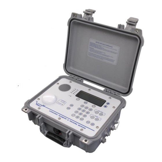
Page 87: Vr100 Specifications
9.3 VR100 Specifications Product name VR100 Ultrasonic Telemetry & Tracking Receiver Frequency Range 12 to 200 kHz Operational between -15°C and +40°C, although battery life will be reduced Operating Temperature below 0°C. Recommended operation is between 15°C and 25°C. Water in which a hydrophone is submerged should not freeze. -
Page 88: Warranty And Disclaimer
VEMCO’s liability, and the Buyer’s exclusive remedy under this warranty, as to a defect in material or workmanship, is limited to the repair of such defect in the accessory, equipment or part in which the defect appears or, at VEMCO’s option, to the replacement of such accessory, equipment or part with a similar item free from defect. As to any item repaired by VEMCO or furnished as a replacement by VEMCO, VEMCO’s liability and the Buyer’s exclusive remedy to the repair or replacement of such item for any further defect in material or workmanship,... -
Page 89: Glossary
The Blanking Interval is the length of time (in milliseconds) after an acoustic signal has been received on a given channel in which the VR100 will ignore any subsequent signals on that same channel. This is to eliminate the reception of echoes by the receiver. - Page 90 A low PDOP indicates the satellites are nicely arranged to give a good position. The PDOP may be improved by facing the VR100 GPS antenna towards the equator where more satellites are located.
-
Page 91: Index
View a comma delimited file, 65 Front panel, 7 View a log file, 64 Introduction, 3 Hydrophone, 8, 29, 69 Parts, 4 Connecting to VR100, 5 Channel, 16, 59, 83 Log file, 63 Comma Separated Variable files, 64 Data, 64 Communication...
Need help?
Do you have a question about the VR100 and is the answer not in the manual?
Questions and answers